vent or recirculate pcv


 04-01-14, 03:49 AM
#3
talking head
the engine ( and turbo ) was designed to have a small vacuum drawing a flow through ventilation system .. it used a purge valve at low loads to put the recirced air to the throttle body,, and higher loads it ran the opposite direction and drew towards the aircleaner
it is however difficult without either a switched or passive purge valve.. or a PCV valve to emulate the original low load path without making for vacuum or idle bypass leaks
but it is very simple to put a vacuum on a non vented catch can by routing the highest vacuum nipple on the can to the turbo aircleaner
if you also use the other nipple on the filler neck routed through a one way valve to a rocker cover filter .. ( drawing from filter,, towards filler neck ) then you can even make the system light vacuum , draw through , like mazda intended for the high load circuit
setup like this ,, your turbo wont smoke.. and the oil control rings wont be hammered by building sump pressures
setup like this.. but using oversize nipples and vac lines to and from the filler neck and the can.. and it will cope with excessive blowby on very loose,, very high boosted engines
try that with doing all that instead with your vented type can without a vacuum ,, see how far you go
04-01-14, 09:16 AM
#4
I am thinking about making an oil catch can with the ports on the middle iron, and on the oil filler neck(enlarged to -8, maybe -10) and having it go to my air filter pipe. Thanks
 04-01-14, 08:06 PM
#7
talking head
yes
draw through the filter with one ( through a one way valve ) towards the filler neck
and route the other nipple on the filler neck to your catch can,, and then from the can.. to the turbo airfilter
this makes the system draw through, light vacuum.. much like the original mazda system was intended
.. you need this light vac to allow the oil from both turbo and from the rotors .. to be able to gravity drain back to the sump
sealing the sump.. or just venting it.. is often just not good enough when blowby gets excessive
.. and if you is smart.. and have an extra nipple on the can .. you can route the 3rd fuel line ( vent ) to the can as well
( much better than leaving the vent line to vent fumes at the trailing coil )
Trending Topics
04-01-14, 10:03 PM
#8
yes
draw through the filter with one ( through a one way valve ) towards the filler neck
and route the other nipple on the filler neck to your catch can,, and then from the can.. to the turbo airfilter
this makes the system draw through, light vacuum.. much like the original mazda system was intended
.. you need this light vac to allow the oil from both turbo and from the rotors .. to be able to gravity drain back to the sump
sealing the sump.. or just venting it.. is often just not good enough when blowby gets excessive
.. and if you is smart.. and have an extra nipple on the can .. you can route the 3rd fuel line ( vent ) to the can as well
( much better than leaving the vent line to vent fumes at the trailing coil )
draw through the filter with one ( through a one way valve ) towards the filler neck
and route the other nipple on the filler neck to your catch can,, and then from the can.. to the turbo airfilter
this makes the system draw through, light vacuum.. much like the original mazda system was intended
.. you need this light vac to allow the oil from both turbo and from the rotors .. to be able to gravity drain back to the sump
sealing the sump.. or just venting it.. is often just not good enough when blowby gets excessive
.. and if you is smart.. and have an extra nipple on the can .. you can route the 3rd fuel line ( vent ) to the can as well
( much better than leaving the vent line to vent fumes at the trailing coil )
My original plan was to weld on a big -8 maybe -10 to the oil filler and vent that along with the center iron vent. Your method would not work as well if I put a breather on the center iron port and recirculated the bigger -8 -10 off the oil filler neck, no?
04-02-14, 09:10 PM
#9
talking head
stock sized nipples works at stock boost levels. AOK
.. for bigger boosts and bigger turbo.. upgrade the nipples and lines to 5/16 or 3/8
im using 5/16,, and have the highest nipple mounted into the lid of the filler neck .. no mustard,, and im using LPG fuel.. notorious for its dewpoint and lung mustard
.. for bigger boosts and bigger turbo.. upgrade the nipples and lines to 5/16 or 3/8
im using 5/16,, and have the highest nipple mounted into the lid of the filler neck .. no mustard,, and im using LPG fuel.. notorious for its dewpoint and lung mustard
04-03-14, 09:13 AM
#10
RX-7 Bad Ass
iTrader: (55)
Few misconceptions here.
First off, you should NEVER have a vacuum before the turbo inlet. One would think you would, since the engine is sucking air in, but you aren't. A vacuum is created by a restriction, you have a vacuum in the engine because the throttle plates are restricting air going to the engine. If you have a vacuum at the turbo inlet, you would have a VERY restrictive intake.
You can always test this out - hook your boost gauge up there. It will sit at zero and not move. It's atmospheric pressure.
Now, many stock intakes on cars do have some measure of restriction. Here's a good article about using a manometer to find intake restrictions. Note this measures in inches of water typically, it's VERY sensitive.
AutoSpeed - Negative Boost Revisited, Part 1
Now, the PCV system does need to breathe. The oil pan has hot oil sloshing around in it, this is expanding with heat. That expansion needs to breathe somewhere, if you just cap it off you will pressurize the oil pan and that pressure will find a way somewhere, either dipsticks popping out, pushed into the exhaust past the seals in the turbo, somewhere.
A vented catch can is really all you need. The can will hold any liquid that is carried out of the PCV system and the filter will allow the system to expand and contract with heat. Mazda had it going to the turbo inlet duct because any oil vapors need to be burned by the engine and scrubbed by the cat, they can't be released to the atmosphere due to emissions regulation.
So, stock, the engine is pushing hot vapors from the oil neck to the turbo inlet duct. That is drawn through the engine, burned, and there ya go.
Dale
04-03-14, 10:40 PM
#11
talking head
so send mazda a big bulletin why they have been doing it wrong since the FC rx7??
they run the high load path towards the aircleaner.. at high loads there IS a vacuum at front of the turbo caused by the restriction that is the aircleaner.. fact
mazda didnt vent it.. it is illegal.. emissions wise..
but they also understood oil is hot,, makes its own vapour pressure ,,and casues issues in oil return from rotors and from the turbo
and if you stick a filter over a catch can vent.. it becomes a POSITIVE a pressure in the sump
( as the filter has some restriction )
mazda use flow through ventilation of the sump space .. at low loads its vac source is the TB ( a higher vac than seen at that time in the aircleaner )
at high loads it goes to the aircleaner.. and you tell us mazda did it wrong?
im telling you they knew EXACTLY what and why they where doing it ,, and my advice is more of the same,, ignoring the need for the tricky purge valve for the low load circuit
, just upsized to cope with higher and higher blowbys
PS.. am a qualified process analyst and i have been using home made manometers to tune some twin throttle bikes since 20 yrs ago ,, alongside FC rx7s ..
Last edited by bumpstart; 04-03-14 at 10:43 PM. Reason: PS
04-04-14, 09:33 AM
#13
This is actually where I get a little confused. Piston engines the combustion gases and fuel can pass through the piston rings and little from valve seals. I'm trying to think of the crankcase for the rotary. Ahhh, through the side seals and between the 2 rotors, back down into the crankcase? I haven't looked at my actual engine much. Can't be through the rotor housings, must be through the side housings
04-04-14, 04:08 PM
#14
A few points: Besides the FD which had that model year change on the PCV, if you look at basically every crankcase ventilation system for turbo cars they all work the same way.
Under boosted conditions, crankcase vapors are pushed out by crankcase pressure to before the throttle plate/before the turbo
Under low load, non boosted conditions, crankcase vapors are drawn out of the engine by manifold vacuum, while filtered fresh air circulates in.
The most important part, for our purposes, is letting the air escape from the crankcase under boosted conditions somehow. The rest is debateable when you don't care about emissions or oil dilution.
As for vacuum in front of the turbo, I have done a lot of testing of this on turbo engines. If you use a pressure transducer and read absolute pressure, the absolute pressure will drop exponentially as mass flow through the turbo increases. At part load it's basically 0. When you are flowing 200, 300, or more grams/sec , your absolute pressure could drop from ~100 kPa to some number that is proportional to the restriction. It could be 95, 92, 88, whatever. More mass flow or more restrictive intake = more vacuum in front of the compressor. It doesn't seem like a lot, but it affects operation of the turbo on the compressor map. The more restrictive the intake, the harder the turbo will work by having a higher pressure ratio and faster turbine speed. The affect of this vacuum on crankcase ventilation is going to be application specific.
04-04-14, 10:59 PM
#15
Senior Member

I don't know about the earlier models, but the FD PCV system can't be very effective at relieving crankcase pressure due to the small size of the nipple and hose.
This is an illustration I made based on the FD workshop manual.

Clearly there is no path for flow through ventilation and simply the positive pressure inside the crankcase finds it's way to the inlet tract so that the vapors can burn in the combustion process. I would imagine that as boost increases the pressure in the crankcase must increase significantly.
As far as pressure drop in the turbo inlet. I'd hope that anyone that is looking for more performance would not have 12kPa (1.74psi) drop across the filter. That's more than double what I use for testing on my flow bench! And just wasting turbo effort for naught.
To the original question as to which is best, I'd say there would be some slight benefit pressure wise to vent to the turbo inlet, but to take advantage of it on a higher boost application you'd need to use at least a -8 size hose and I'd implement some form of oil separator to minimize oil in the boost tract.
This is an illustration I made based on the FD workshop manual.
Clearly there is no path for flow through ventilation and simply the positive pressure inside the crankcase finds it's way to the inlet tract so that the vapors can burn in the combustion process. I would imagine that as boost increases the pressure in the crankcase must increase significantly.
As far as pressure drop in the turbo inlet. I'd hope that anyone that is looking for more performance would not have 12kPa (1.74psi) drop across the filter. That's more than double what I use for testing on my flow bench! And just wasting turbo effort for naught.
To the original question as to which is best, I'd say there would be some slight benefit pressure wise to vent to the turbo inlet, but to take advantage of it on a higher boost application you'd need to use at least a -8 size hose and I'd implement some form of oil separator to minimize oil in the boost tract.
04-05-14, 08:22 AM
#16
Arrogant Wankeler
Anyone venting to a venturi spike in the exhaust? Did this on my diesel (post catch can). I figure on anything with a modest size turbo it is giving you every last bit of intake volume for clean cool air rather than what is effectively dirty wet EGR which coats your intake track reducing intercooler efficiency. Exhaust temps should keep any remaining vapour in suspension, might not be great for anyone with EPA inspections on their vehicle.
04-06-14, 04:04 AM
#17
talking head
funny you should mention it, as someone proposed an exhaust venturi to me just yesterday
it certainly negates the potential to have some vapour wetting the intercooler
but i expect without special consideration for the design of the venturi
in some conditions it may make for low or reversed flow , or fumes potential to the driver
i would think you would have to plumb in after a muffler, using the pressure drop and cooling it naturally provides
( sits back and waits for the smoke screen on shut throttles )
Last edited by bumpstart; 04-06-14 at 04:09 AM.
04-07-14, 12:04 PM
#18
Here is an example showing different restriction curves on a number of turbo engines... these are more restrictive intake systems than clamping on a K&N to your GT35R but it illustrates the point I'm making. There really is a significant pressure difference between the crankcase and the turbo inlet. This pressure difference could be drawing crankcase vapors out under heavy load, but it's dependent on mass flow. It's not nearly as much drop as you get across the throttle valve at part load (50 kPa manifold vs 98 kPa atmospheric, so 48 kPa drop) but it's still significant.

funny you should mention it, as someone proposed an exhaust venturi to me just yesterday
it certainly negates the potential to have some vapour wetting the intercooler
but i expect without special consideration for the design of the venturi
in some conditions it may make for low or reversed flow , or fumes potential to the driver
i would think you would have to plumb in after a muffler, using the pressure drop and cooling it naturally provides
( sits back and waits for the smoke screen on shut throttles )
it certainly negates the potential to have some vapour wetting the intercooler
but i expect without special consideration for the design of the venturi
in some conditions it may make for low or reversed flow , or fumes potential to the driver
i would think you would have to plumb in after a muffler, using the pressure drop and cooling it naturally provides
( sits back and waits for the smoke screen on shut throttles )
04-07-14, 10:08 PM
#19
Arrogant Wankeler
BTW my system only vents to the exhaust, not intake.
EGR soot builds up on manifold walls and ports, blocks map sensors and destroys bores. Given the research i have seen on NOx and hydrocarbon emissions rising from diesels after they have a reasonable in service carbon build up on piston/head I would suggest that the NOx reductions seen on new engines running EGR are all but lost over time anyway, so you are left with an engine failure point (EGR cooler) which also reduces engine life by accelerated wear.
EGR soot builds up on manifold walls and ports, blocks map sensors and destroys bores. Given the research i have seen on NOx and hydrocarbon emissions rising from diesels after they have a reasonable in service carbon build up on piston/head I would suggest that the NOx reductions seen on new engines running EGR are all but lost over time anyway, so you are left with an engine failure point (EGR cooler) which also reduces engine life by accelerated wear.
04-11-14, 10:11 AM
#20
Im planning on a road draft tube (emissions be damned!). Got a little filter on the filler neck (13bt) and a line running from the center iron down to below the car. Im thinking of fitting a small funnel on there to draw a bigger vacuum.
anyone have experience running a road draft?? Its as oldskool as crankcase venting gets but its clean and simple.
anyone have experience running a road draft?? Its as oldskool as crankcase venting gets but its clean and simple.
04-13-14, 11:31 AM
#22
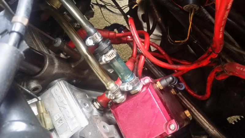
This is how I run it on my FC.
The large line is a check valve that is pulling vacuum from the lower intake manifold.
The small line is attached to the center iron.
Fresh air comes from the oil filler cap. Its not a perfect seal so air is pulled in from there.

The large line is a check valve that is pulling vacuum from the lower intake manifold.
The small line is attached to the center iron.
Fresh air comes from the oil filler cap. Its not a perfect seal so air is pulled in from there.

Thread
Thread Starter
Forum
Replies
Last Post