Two Fuel Pumps - one to each rail or....?
 06-09-03, 03:33 PM
#26
Got Boost?
Well, If you're interested, I could probably design a entire checking system, but priliminarily here is a circuit that makes an output linearly related to the difference in the current flowing to each fuel pump.
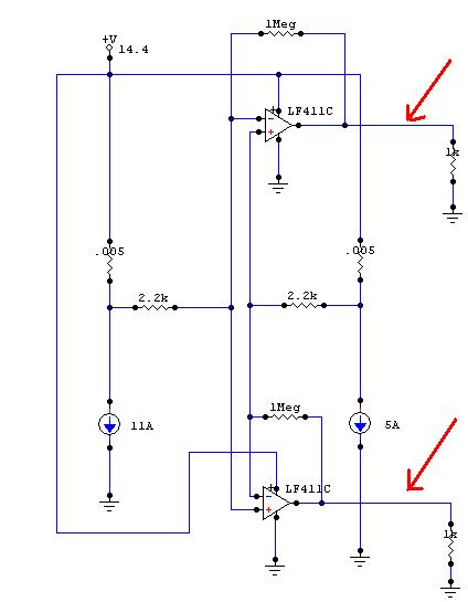
The current sources (the circles with the arrows through them) represent the fuel pumps. Using a very small precision current sencing resistor, I can measure the current by measuring the voltage drop across it. The .005 ohm resistors with a 20A load only drops the voltage at the fuel pumps by .1V. ( Note: I chose this, because there's a .005 Ohm resistor made by ohmite that is only $1.55 a peice that Digikey.com sells, but you could go with a high precision .001 Ohm by the same company for around $10 a resistor, this would make the voltage drop across it @20A only .02V, but this system would potenially more jittery due to noise)
The Op-amps( the triangle things with the + and - on them) I use to measure the voltage drop across the two resistors relative to each other. With the resistor values I have shown, the output is where the red arrow show. The voltage between these two arrows will go from +11V with 5A biased to fuel pump one, down linearly to 0V when they are flowing equal electrical current, and -11V when 5A is biased to fuel pump two. From here it would be pretty easy to massage this linear signal to turn on warning lights, or power a guage.
When a pump dies, the current in it will slowly increase due to it trying harder to pump, due to the mechanical resistance increasing. Eventually either the fuse will blow, or the pumps electrical circuit will fry (opening up, and stopping current flow). With this sort of a system, you could monitor the relative strain of the pumps, and would give you indication before the pump goes, that it is on its way out, and would still be easy to see when it actually does.
Last edited by fatboy7; 06-09-03 at 03:36 PM.
 06-09-03, 04:48 PM
#27
Rotary Freak
Join Date: Feb 2001
Location: MN
Posts: 2,524
Likes: 0
Received 0 Likes
on
0 Posts
Originally posted by shawnk
The thing about that is if the pump stops the check valve will hold pressure in that segment. Now when you turn off the car (pressure loss in system allows check valve to open and depressurize) and then turn it back on you would be able to detect the loss. Where can you find a pressure switch like you are talking about? 6AN (3/8" ID) maybe 25psi rated. I am still leaning toward a completely electrical monitor but I am starting to realize how much of my college physics I have lost over the years. I started a very similar drawing and will post tonight.
I also think I have decided to run the pumps on high all the time to simplify the system.
Welcome to the discussion setzep.
Shawn
I'm not sure where you can buy a pressure switch like that but I bet mcmaster.com would be a good place to start. I have one here but it's adjustable from 1000-3000psi so I don't think that will do much good
 06-09-03, 04:53 PM
#28
Rotary Freak
Join Date: Feb 2001
Location: MN
Posts: 2,524
Likes: 0
Received 0 Likes
on
0 Posts
Woah fatboy7! Someone has some electrical engineering knowledge under his belt 
But when a pump starts to die won't most likely draw less current due to it pumping less (less VE)? Unless you are saying the motor itself dying then I can see how it could start to draw more current.
But when a pump starts to die won't most likely draw less current due to it pumping less (less VE)? Unless you are saying the motor itself dying then I can see how it could start to draw more current.
06-09-03, 05:05 PM
#29
Perpetual Rebuilder
Thread Starter
Umm i have no idea what that drawing is but it sure looks impressive...I am on my way out the door at work so dont have time to grok it. I have been riding the company time clock and working on my drawing and wanted to upload before I leave. Here is what I came up with. My idea now is to put a relay behind the pump and hook it to ignition and a green led for each pump and mount them right near the fuel pressure gauge. That way both would be green if both pumps on. Let me know if this is electrically possible.

Shawn
Shawn
06-09-03, 05:26 PM
#30
Rotary Freak
Join Date: Feb 2001
Location: MN
Posts: 2,524
Likes: 0
Received 0 Likes
on
0 Posts
You have your switches drawn wrong but I think I see what you are after. So you only want the lights to be on when they have power going to them? What heppens when they have power to them but they aren't doing any work (ie when they go bad)?
06-09-03, 05:42 PM
#31
Rotary Freak
Join Date: Feb 2001
Location: MN
Posts: 2,524
Likes: 0
Received 0 Likes
on
0 Posts
just looked at mcmaster.com and sourced out a pressure switch for ya . Go there and look for p/n 3460k13. It's a adjustable pressure switch from 6-30psi and it's under $20. Compact design and 1/8" pipe, what more can you ask for?? Oh yeah they also have check valves for under 20 bucks also that should do the job. Man I should be getting payed for all this application engineering!
. Go there and look for p/n 3460k13. It's a adjustable pressure switch from 6-30psi and it's under $20. Compact design and 1/8" pipe, what more can you ask for?? Oh yeah they also have check valves for under 20 bucks also that should do the job. Man I should be getting payed for all this application engineering!
06-09-03, 06:08 PM
#32
Got Boost?
But when a pump starts to die won't most likely draw less current due to it pumping less (less VE)? Unless you are saying the motor itself dying then I can see how it could start to draw more current.
Simply put, when a electric motor freely spins w/o a load, it draws very little current, but turns at its maximum rpm. The more the load placed on the motor the slower it turns, and the more current it draws, until it completely stops, when it draws the most current. Basically electric motors are constant HP motors. This is also why fuel pumps flow less fuel at higher pressures, more load, less rpms, less fuel.
At a given pressure two identical pumps should be under the same load (obviously not possible due to manufacturing tolerances). However when one pump starts to die, it has to try harder to pump at the same pressure as its healty neighbor, so its load increases, rpm decreases (as does fuel flow slightly) to keep up, thus the current draw will be higher. This is how you can tell a sick pump. Eventually it just won't be able to keep up and will likely freeze up. At this point the current draw will be the highest. But it will only last breifly like this, because fuel pumps aren't meant to run that much constant current, especially without the fuel cooling the pump. So after a very short period of time the a portion of the coil wires will melt and/or vaporize and the circuit will stop flowing almost completely. So yes, when it fails the current will drop off almost entirely, but up to the point of failure, you notice the current get progressively higher.
06-09-03, 06:16 PM
#33
Got Boost?
Shawnk, the problem with relays, is finding one where the voltage drop, and acceptible current flow will not hamper the fuel pumps operation. Normal 12V relays want to see 12V by themselves, and most relays only want to see a few hundred milliamps. Fuel pumps in normal usage will draw anywhere from 2A-15A, and also like to see as much voltage as possible. The system I drew above is designed to only absorb >1% of the power from the system, relays unless massive and custom just won't cut it. Essetially though, your idea and my idea are one in the same: monitor the current draw to the fuel pumps.
06-09-03, 06:39 PM
#34
Rotary Freak
Join Date: Feb 2001
Location: MN
Posts: 2,524
Likes: 0
Received 0 Likes
on
0 Posts
I'm not sure you understand what I'm talking about. I guess I worded it wrong. What I meant was when a pump goes bad (the pumping device whether gerotor, vane, gear ect... ) it wont draw as many amps. I wasn't talking about the electric motor itself. If it was the actual pumping part of the pump that went bad how could you montor that? Maybe a electrical circut that read when the amps were too low?
Last edited by setzep; 06-09-03 at 06:42 PM.
06-09-03, 06:46 PM
#35
Got Boost?
OIC what you meant. Like if the pump somehow lost compression, but continued to freewheel spin?
The circuit I drew above just measures the difference in current between the two pumps. That means it works both ways, too much or too little. Unless of course both die at the same time...... Knowing exactly which pump is dead or dying is probably best tested with the car turned off and on jack stands. This would just help you know when one of your pumps is doing something out of the ordinary.
The circuit I drew above just measures the difference in current between the two pumps. That means it works both ways, too much or too little. Unless of course both die at the same time...... Knowing exactly which pump is dead or dying is probably best tested with the car turned off and on jack stands. This would just help you know when one of your pumps is doing something out of the ordinary.
06-09-03, 08:29 PM
#36
Rotary Freak
Join Date: Feb 2001
Location: MN
Posts: 2,524
Likes: 0
Received 0 Likes
on
0 Posts
ahh IC, I don't speak electronics so I didn't see that it works both ways But like you said if you lost both pumps (wires got cut or something) you'd be screwed? Man my simple pressure switch idea is looking good right about now
But like you said if you lost both pumps (wires got cut or something) you'd be screwed? Man my simple pressure switch idea is looking good right about now
06-09-03, 09:01 PM
#37
Perpetual Rebuilder
Thread Starter
I was going for simple so green light = good, no light = bad. And I was making the assumption that a dead pump will pass no current. Of course my simple solution doesnt tell if the pump is failing which could be just as bad. But the truth is fatboy's solution is probably over my head. Removing the check valve on the pump is a good idea and that makes the 2 gauge / check valve system feasible.
You look like you enjoy electical stuff fatboy7. Wanna put one together and I will implement and test it? I am willing to finance the project and put it in my car. What do you say?
Shawn
You look like you enjoy electical stuff fatboy7. Wanna put one together and I will implement and test it? I am willing to finance the project and put it in my car. What do you say?
Shawn
06-11-03, 12:51 PM
#38
Rotary Freak
Join Date: Nov 2001
Location: trinidad and tobago
Posts: 2,715
Likes: 0
Received 0 Likes
on
0 Posts
Why not just place a pair of voltmeters in the pump/s circuits so you can monitor the current draw , the amount of amperage is a direct indication of work or lack of work.
06-11-03, 03:47 PM
#39
Perpetual Rebuilder
Thread Starter
Well I could do that but not sure where I would mount those. If fatboy7 doesnt return to this thread then I may have to go that way or the check valve way...
Any other electronics guys who can use fatboy7's drawing to put something together?
Shawn
Any other electronics guys who can use fatboy7's drawing to put something together?
Shawn
06-12-03, 12:22 AM
#41
Got Boost?
What kind of output do you want..... a simple led that lights when things are out of the ordinary, or a gauge? The led thing would be the cheapest, but will be harder to set properly. The electronics would actually be easier to construct, but I don't know what amperage difference I would have to set it to, in order to give adequate warning, while not being overprotective/sensitive to normal use. A gauge is better in that the driver decides when something is wrong, but which gauge should I use (ie take apart and rig its guts.)?
It would probably cost around $40-50 for the box and the warning light, more if using a gauge..... let me know if you're interested.
It would probably cost around $40-50 for the box and the warning light, more if using a gauge..... let me know if you're interested.
06-12-03, 07:21 AM
#42
Perpetual Rebuilder
Thread Starter
Well I probably will want to end up with a simple LED (or maybe a not-so simple LED - they make LED's that can show 2 different colors right? so maybe a "something is up color" and a "big problems color").
But I understand the inherent problems you will have building it because we have no idea where to start as far as what will be normal and what needs attention. If you can think of a way to build it and maybe hook it up to a cheap digital lcd I could test it with a couple different pump setups (I now have 3 stock pumps and will probably pick up another one for testing) and then once we see what is normal change the output to LED. Maybe build it in 2 parts that way you could build the second output part and send it to me and I can disconnect first output part and attach the new setup. I am willing to go $100 (or a little over on this experiment) you think it can be done for that much?
Also I know you are busy and have your own projects so how long do you think you'd need to fit something like this into your schedule? I am puttering around town on my stock pump and can continue to do so but I am starting to get pissed everytime those mustang boys pull up and rev at me and I have to ignore them rather than enlighten them.
Thanks,
Shawn
06-12-03, 11:11 AM
#43
Got Boost?
Here, I'll tell you what.... I can set it up to use a two color led, one set to what I would consider a warning (like set it to 2A difference), and also a danger level ( something around 4A difference). You can try it when you get your pumps. Sense they'll be new, I hope, you can test it, if either light up under normal conditions, we can figure out some way to make it work. That sound good?
Like I said, it should come out around $50 for the materials. A little for my time would be nice, $100 would definately to the trick. Like most electronics the first one is the most expensive ('cause there is likely to be several itterations), the cost for a second would be much less, proably almost half. So, if we can find anyone else interested..... the price will come down.
As far as time is conserned. I do have a project that I'm working on, but this souldn't take too long to do, once I get all the parts, I could have it done by mid July at the latest.
Like I said, it should come out around $50 for the materials. A little for my time would be nice, $100 would definately to the trick
. Like most electronics the first one is the most expensive ('cause there is likely to be several itterations), the cost for a second would be much less, proably almost half. So, if we can find anyone else interested..... the price will come down.As far as time is conserned. I do have a project that I'm working on, but this souldn't take too long to do, once I get all the parts, I could have it done by mid July at the latest.
06-12-03, 12:35 PM
#44
Perpetual Rebuilder
Thread Starter
All the pumps I have are used so this will be a real world situation right off the bat. I am willing to give it a try with the LED and have no idea if the 2 and 4 would be good (but a false negative is better than a false positive in this case). I'd also be glad to give you money for your time and would be willing to send you $100 today but mid july is a little far out for me. I have had all the stuff to do this conversion since I started this thread and another 5 weeks would begin to be painful - 3 weeks out would be alot better. You think you can do it?
Shawn
Shawn
08-22-04, 09:05 PM
#48
Perpetual Rebuilder
Thread Starter
I did end up getting the electrical box from fatboy. I could ever get it to work right and started having problems with the dual pump setup (couldnt get a good seal on the extra holes I drilled in the pump assemble top). I ended up pulling all that stuff out and going back to a single cosmo pump running in series to the rails.
I could however tell very easily with a simple fuel pressure gauge when one of the pumps was off. I had a stock pump I used fail and the car would hardly idle and ran like crap. I still dont recommend dual pumps if you are going for anything less than 400 rwhp.
I could however tell very easily with a simple fuel pressure gauge when one of the pumps was off. I had a stock pump I used fail and the car would hardly idle and ran like crap. I still dont recommend dual pumps if you are going for anything less than 400 rwhp.

Thread
Thread Starter
Forum
Replies
Last Post
Skeese
Adaptronic Engine Mgmt - AUS
65
03-28-17 03:30 PM