
My custom upper intake manifold! *With pictures*


 07-15-08, 05:07 PM
#3
Learned alot | Alot to go
iTrader: (2)
Join Date: Apr 2002
Location: Rotaryland, New Hampshire
Posts: 4,232
Likes: 0
Received 0 Likes
on
0 Posts
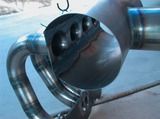
Any photo's inside the plenum? specifily where the individual runners meet the plenum? Everyone seems to have a different way of doing it, im always curious to see yet another way.
07-15-08, 06:21 PM
#4
Other peoples designs were cheaply made and lacked proper sizing. My setup is geared toward my 42r setup. It incorporates flush velocity stacks, wide radius bends, and a properly sized plenum. It wasn't a cheap project but I'm more than happy with the outcome! I doubt I could produce these as they utilize A LOT of machined parts.
07-15-08, 09:17 PM
#7
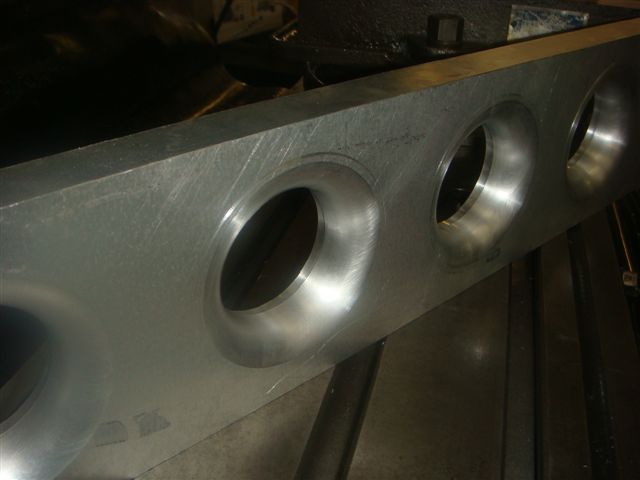
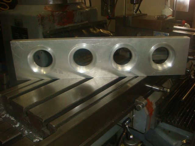
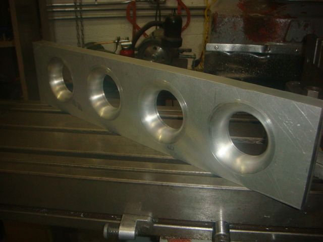
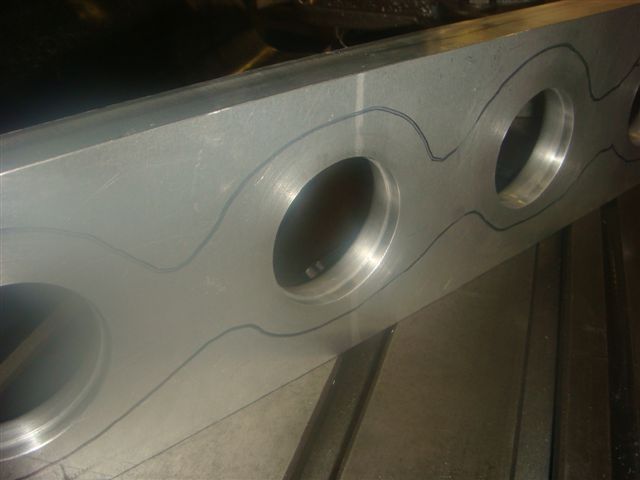
The first shot is the flush mounted velocity stacks machined to my spec's. Second are some shots of the flange I used to mate to the lower. It has .002" recess to keep the tubing centered with out using a tube to telescope. More pictures will come when I have time. Thanks for looking!


Trending Topics
07-15-08, 10:11 PM
#9
The first shot is the flush mounted velocity stacks machined to my spec's. Second are some shots of the flange I used to mate to the lower. It has .002" recess to keep the tubing centered with out using a tube to telescope. More pictures will come when I have time. Thanks for looking!
07-15-08, 10:24 PM
#11
Yes, the welding was done by yours truly. Not my best work, my Miller 250 DX Syncrowave took another dump (I'm going to sell it soon). I had to get out the oldschool Lincoln 175 NON WATER COOLED. Anyway, I'm honestly down to just welding up the rest of the 4" v-band exhaust and wiring up the throttle position sensor and we're good to roll! I'll get the plenum volume to later via pm. It's finally time for me to sleep.
Last edited by mono4lamar; 07-15-08 at 10:29 PM.

 07-16-08, 06:39 PM
#16
Rotary Freak
Join Date: Dec 2001
Location: chandler, AZ
Posts: 2,402
Likes: 0
Received 0 Likes
on
0 Posts
Similar basic design concept except I went with a one-piece manifold and obviously steel..
Inside:
All done and powdercoated:
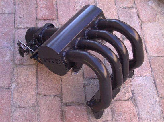
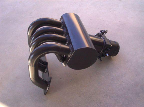
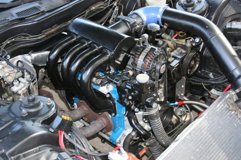
Installed post revisions and still n/a... (thicker engine flange and added tapered sections before the bends into the motor..)
Inside:
All done and powdercoated:
Installed post revisions and still n/a... (thicker engine flange and added tapered sections before the bends into the motor..)
07-17-08, 06:48 AM
#20
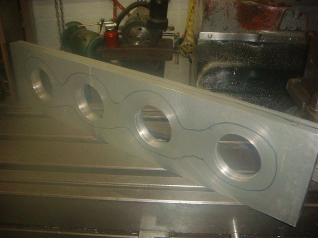
I love people are pming me thinking I copied someones design. This is obviously not the case so I'll spell it out for the non technical thinkers here. You have to have a 90 degree bend to meet the lower intake and obviously you should have a plenum. My plenum volume is calculated... Not just cut and thrown on. Also my runner ID's and lengths have been accounted for. I'm using velocity stacks unlike a taper like everyone else's manifolds. As for the flanges the tb flange is 1" thick and the upper to lower intake flange is 1/2"! The acual plenum itself is 1/2 drawn aluminum. All of these components and tubing are all from high grade 6061 aluminum.
07-18-08, 10:39 PM
#21
I love people are pming me thinking I copied someones design. This is obviously not the case so I'll spell it out for the non technical thinkers here. You have to have a 90 degree bend to meet the lower intake and obviously you should have a plenum. My plenum volume is calculated... Not just cut and thrown on. Also my runner ID's and lengths have been accounted for. I'm using velocity stacks unlike a taper like everyone else's manifolds. As for the flanges the tb flange is 1" thick and the upper to lower intake flange is 1/2"! The acual plenum itself is 1/2 drawn aluminum. All of these components and tubing are all from high grade 6061 aluminum.
Don't worry about the haters. They just don't posses any fabrication skills. The majority of the fabricated manifolds are going to look similar.
07-19-08, 01:22 AM
#22
Yeh from the outside only where it does not matter! 
Here are my copies also!
And for the copy cats here's something new to copy!


Here are my copies also!
And for the copy cats here's something new to copy!
Last edited by crispeed; 07-19-08 at 01:40 AM.