Building a custom UIM, thoughts wanted!
 10-07-08, 03:03 PM
#1
506 RWHP 12A..
Thread Starter
Building a custom UIM, thoughts wanted!
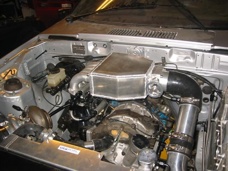
First off, lets start with the engine. Its a 12A Turbo, large street ports, tallport center, race exhaust ports... Not a street car, primarely built for trackdays and such, so streetabilaty is second to performance.. TII intake manifold on ASK adapter.
Im in the process of building a new upper intake manifold/plenum and i thought i would get some more input on sizing e.t.c before this thing gets put together. Im basically using 4 90 degree pipes from the LIM to the plenum, with enough lenght to clear my fuel rail. Runner sizes is 38mm for the primarys, and 45 for the secondarys. The runners enters the plenum and ends in bellmouths. Here comes the tricky part.. Im thinking of making the primarys longer than the secondarys, inside the plenum, hoping this could benefit pulse tuning and widen the powerband. The plenum would be a square box, that narrows down to TB size at the end, like Hogans intake manifolds, if someone has seen them.
Now, question time!
- When calculating plenum volume, i have heard that anything between 0,8 up to double the volume of the engine works. But whats correct for a rotary? Should i calculate the engine as a 1146 ccm engine or a 2292 ccm?
- Cam duration. Well its a large street port and race exhaust.. How about 260-280?
- TB sizing. Whats too large/small? The one i have is 90mm, and i know its going to be a hassle, but im planning on compensating by modulating the throttle pull.
Any other comments and useful tips are greatly appreciated! Ill post some pics when i start assembling it, and post them here.
 10-08-08, 08:40 AM
#3
I'd personally build a new lower intake manifold as that's where your biggest problem is. An adapter that mates a 13B manifold to a 12A is always going to result in a compromise in performance and a new upper can't change that.
A 90mm throttlebody is way too large. People have a gendency to go with tb's that are larger than what they need. I've used up to a 75mm throttlebody and it's plenty large. I'd actually prefer to go smaller but I'm backwards from many people. I also believe that turbo engines could benefit from longer intake runners than n/a's.
Don't try to overthink the intake by lengthening certain runners and not others. Once you are in boost, the turbo is doing all the work anyways. Keep it simple. Make them equal.
As far as plenum sizing goes, don't get too caught up on numbers. If this isn't a street engine, go as large as you can. If it can get obscenely large, do it. You'd have to get over 15X larger than the engine (2.4L) before going still larger does nothing else. That's pretty big!
10-09-08, 09:55 AM
#4
506 RWHP 12A..
Thread Starter
First of, i did search, and i have read all of Rotarygods thread on calculating intake runners.. Thanks for the excellent thread by the way!
I also forgot to mention that a LIM would be next, but for now, the stock intake would have to do. Its also a RHD car, and space is very confined on the turbo/intake side..
The positioning of the stacks is also a space issue, i dont really care about a hole in the hood, but i kinda dont want to move the engine forward, just to gain some spacing between the stacks.. That said, i have read different opinions about the spacing around the stacks. Some say that flush mounting and very little spacing between them works best, while others say that you should allow for about half the diameter of the stack itself in spacing between plenum sides and so on.
Im also planning on using a reverse mounted stack, that goes from the TB inlet of the plenum and spreads out facing the runners inside the plenum, to distribute the flow less turbulent. Any point doing this, or am i just wasting my time?
Ill try and make a drawing in CAD, and explain what i mean.
I would appreciate any educated answers!
10-31-08, 10:53 AM
#5
506 RWHP 12A..
Thread Starter
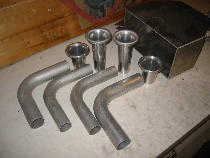
Got my tubes, tb and bent/cut some of the parts for the plenum. Also got my trumpets. Still waiting on bellmouth for the TB and flanges. Im making two, so that i can match a lower manifold later on.
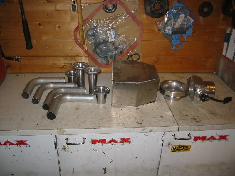
The pictured bellmouth is not mine, just put in in there to guesstimate size and soforth. Machining required..
Im also going to cut down the height of the plenum itself, to about the height of the TB.
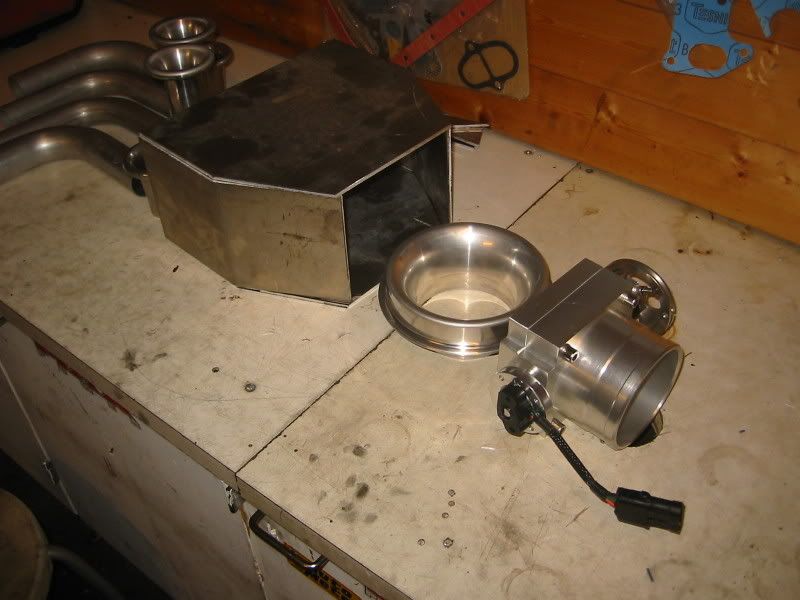
Trumpets.. Real nice finish on these..
Also, i might as well add some vacuum ports on the plenum, and maybe even a idle speed motor..
Just have to get the last pieces, and then its time to weld this baby up!
The pictured bellmouth is not mine, just put in in there to guesstimate size and soforth. Machining required..
Im also going to cut down the height of the plenum itself, to about the height of the TB.
Trumpets.. Real nice finish on these..
Also, i might as well add some vacuum ports on the plenum, and maybe even a idle speed motor..
Just have to get the last pieces, and then its time to weld this baby up!
Trending Topics
11-02-08, 05:10 AM
#9
talking head
https://www.rx7club.com/naturally-aspirated-performance-forum-220/tb-question-custom-intake-795674/


dimensions of barrel on the plenum added to the s4 LIM
100 mm diameter
(rhomboid? ) shape ( triangle taper at ends, long-side is throttle side)
long length..250 mm
short side length (turbo side) 200mm
75 mm centre entry , angled slightly up focused at primary runners
60 mm single blade GM TB ( will interchange with a 65 mm similar unit )
all up, the volume just in the the plenum and its entry ( but not the LIM )
would be close to 2L
these dimensions didn't noticeably lose response to the low end of a stock set up when driven progressively on the throttle
( the tip in movement of the TB proved sensitive though )
though they did noticeably improve the flat spot above 6000 rpm that begins to occur with stock manifolds
- it breathed much better at higher RPM's , despite the apparently smaller TB arrangement
also, here are some pics i stole from paul cochrane on ausrotor
he has done a magnificent job
he was also ( like me ) seeking more volume suit a propane mixer
i would hazard and say his added volume for the plenum would be closer to 3L
Last edited by bumpstart; 11-02-08 at 05:13 AM.
11-02-08, 06:01 PM
#10
Full Member

Join Date: Apr 2008
Location: san fransisco
Posts: 162
Likes: 0
Received 0 Likes
on
0 Posts
Ok , im using the same size pipe and 80mm TB, but i will be utilizing a dual plenum to equalize flow to the runners. I will be doing the whole intake manifold though.. not just the upper or lower.
11-02-08, 06:17 PM
#11
Lives on the Forum
I know it's a little late for this, but if you're doing your own manifold, why limit yourself to the stock ruuner size (especially for the primaries)? Why not do it all now and run larger tubes for more flow potential?
11-02-08, 11:17 PM
#12
Full Member
Join Date: Apr 2008
Location: san fransisco
Posts: 162
Likes: 0
Received 0 Likes
on
0 Posts
11-03-08, 03:56 AM
#13
506 RWHP 12A..
Thread Starter
11-03-08, 09:25 AM
#14
Full Member
Join Date: Apr 2008
Location: san fransisco
Posts: 162
Likes: 0
Received 0 Likes
on
0 Posts
i mean something simular to this http://images.google.com/imgres?imgu...3Doff%26sa%3DN
11-03-08, 01:18 PM
#15
That's a design that Audi developed for the Quattro rally car. They also ran that style of a plenum on the R8 LeMans car which was replaced by the current R10. They refer to it as a "dual tapered plenum". It's a good design if you can get right. Here's a link that shows several Audi manifolds. The first few on the page are not dual tapered plenums so scroll down a little bit.
http://www.bufkinengineering.com/intake%20manifolds.htm
http://www.bufkinengineering.com/intake%20manifolds.htm
Last edited by rotarygod; 11-03-08 at 01:23 PM.
11-03-08, 01:34 PM
#16
On flats
iTrader: (29)
Join Date: Oct 2004
Location: Albuquerque
Posts: 1,379
Likes: 0
Received 0 Likes
on
0 Posts
If you wouldn't mind elucidating how one "get's it right", I, for one, would be very grateful. I understand that this is a very complicated thing without a perfectly straightforward, one size fits all, answer, but just a few pointers and as much explanation as you'd be willing to provide sure would be good reading. I've read almost all of your posts regarding intake design (I think), and haven't found much in the way of this type of design.
If you don't feel like typing up a drawn out response, I understand. . .a few recommended resources would be greatly appreciated.
If you don't feel like typing up a drawn out response, I understand. . .a few recommended resources would be greatly appreciated.
11-03-08, 01:57 PM
#17
Full Member
Join Date: Apr 2008
Location: san fransisco
Posts: 162
Likes: 0
Received 0 Likes
on
0 Posts
That's a design that Audi developed for the Quattro rally car. They also ran that style of a plenum on the R8 LeMans car which was replaced by the current R10. They refer to it as a "dual tapered plenum". It's a good design if you can get right. Here's a link that shows several Audi manifolds. The first few on the page are not dual tapered plenums so scroll down a little bit.
http://www.bufkinengineering.com/intake%20manifolds.htm
http://www.bufkinengineering.com/intake%20manifolds.htm
11-03-08, 02:47 PM
#18
Though that might be "neat" and usefull for feeding multiple cyclinders equally whilst being able to side feed it, I see ZERO use for it on a 2 rotor wankle engine (reffering to the dual plane tapered plenium) . All you have to do is straight feed it to eliminate all the gadgetry (your not feeding 4,5 or 6 individual cyclinders, ONLY 2). All your looking to do is keep front to rear rotors equal, not so much primary to secondary, as they will take in the air they essentually want on their own. Don't over complicate things, because this is were complicated math gets you into a target, and actual research and testing gets you the desired results. Unless you have no job, tons of material to fabricate over and over not to mention expensive testing equipment.
~Mike..........
~Mike..........
Last edited by RacerXtreme7; 11-03-08 at 02:50 PM.
11-03-08, 03:59 PM
#19
Full Member
Join Date: Apr 2008
Location: san fransisco
Posts: 162
Likes: 0
Received 0 Likes
on
0 Posts
Though that might be "neat" and usefull for feeding multiple cyclinders equally whilst being able to side feed it, I see ZERO use for it on a 2 rotor wankle engine (reffering to the dual plane tapered plenium) . All you have to do is straight feed it to eliminate all the gadgetry (your not feeding 4,5 or 6 individual cyclinders, ONLY 2). All your looking to do is keep front to rear rotors equal, not so much primary to secondary, as they will take in the air they essentually want on their own. Don't over complicate things, because this is were complicated math gets you into a target, and actual research and testing gets you the desired results. Unless you have no job, tons of material to fabricate over and over not to mention expensive testing equipment.
~Mike..........
~Mike..........
11-03-08, 04:17 PM
#20
NO, your feeding 2 PAIRS of 2. All your concerned is front to rear equalization (2 sources of air injesting), as I already stated, the primaries and secondaries will take what they need. All you have to do is keep the front pairs the same as the rear pairs (again, TWO SOURCES). If you like complicated gimicks to solve a simple solution then go for it. I like seeing unique creations. I'm just a form follows function guy though and keeping things simple usualy works best in the end.
~Mike............
~Mike............
11-03-08, 04:50 PM
#21
506 RWHP 12A..
Thread Starter
I have been getting some pms about where i got my parts, so here is a list:
- Bellmouths are from www.velocity-of-sound.com
- TB is from Ebay
- Tubing is from mandrelbendingsolutions.com
- The rest is sourced locally, its basically just 4mm aluminium..
I drew the flange where the LIM meets the UIM in CAD. Its getting cut locally on a waterjet/laser.
BTW. Thanks for the answers!
11-03-08, 04:54 PM
#22
On flats
iTrader: (29)
Join Date: Oct 2004
Location: Albuquerque
Posts: 1,379
Likes: 0
Received 0 Likes
on
0 Posts
When do you think it would begin to be beneficial? What about on a 20B? In my mind, there exists a more real basis for this approach (in the case of the 20B) because there are primaries next to secondaries from different rotors, creating an asymmetry. If they're "fighting" for air, it makes intuitive sense to me that this could result in a potential imbalance that might be remedied (to some degree) by this type of manifold. Now I'm not a fluids engineer; I took just enough fluids, momentum and mass transfer classes to know that something making intuitive sense doesn't necessarily pan out, so I'm looking to be educated here. Thank you kindly for any educated posts.
11-06-08, 12:00 PM
#24
I think there is merit in any good design. Equal distribution isn't as easy as people think it is. None of the stock fuel injection rotary intake manifolds have equal distribution. What I do think is a waste of time and effort is gasket matching and other small things that people do to stock manifolds. They typically "increase flow" in the areas that aren't the restriction and then justify it by saying "every little bit helps". That only applies to helping the worst area though. If you improve an area that already meets your flow requirements while something else is more restrictive, you've done nothing so no every little bit does not always help.
I laugh when I see people imply that you need to spend tons of money and time to get something right. That's where theory comes in. Theory gets you close. Experimentation gets you the rest of the way. Theory makes up for most of the experimentation cost. Good modular design makes up for the rest. It doesn't take a fortune to design most things unless you are trying to create something unknown that's never been done before. This manifold is no different. I applaud people that try different things knowing it may or may not work. It's THOSE people that benefit everyone in the long run and we need more of them.
This manifold is actually quite simple in concept. The most important aspect to getting even flow through it is in the first cone shaped plenum and the size of the slot connecting it to the main plenum. The main plenum is sized to affect powerband. Larger for higher rpms and smaller for lower rpms. Then of course you have runner location within it but that's last to worry about.
I can type up a description of how to go about designing a dual tapered plenum but have never gotten around to it. I'll get to it one day. I no longer have a flowbench though so actually providing test results isn't going to happen right now anyways. In the mean time studying Formula SAE intake manifold designs and problems is one good way to learn. Here's a comparison of a log style intake vs a 4-1 header style intake manifold. It's neat to see how some things make a difference. This one's initial design problem are pretty easy to explain and obvious. It's a wonder they built it that way at all.
http://www.optimalsolutions.us/pdf/B...-Car-Study.pdf
There is even a website from one team somewhere out there that shows their test results with a dual tapered plenum complete with CFD's. I can't find it right now but it's worth searching for if you are interested in designing this type of intake.
01-17-09, 02:01 PM
#25
506 RWHP 12A..
Thread Starter
Its finally done!
I finally got it back from welding! First, the tubing was welded between the flanges, i got it back, port matched it, adjusted the box a little bit and hey presto!
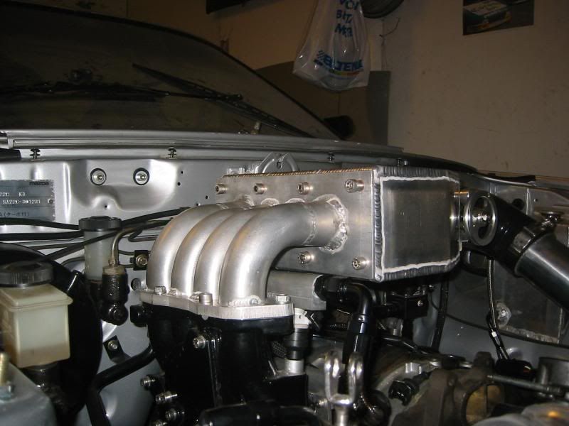
I ended up using a little bit different setup, so had to make cones from the tube diameter onto the box flange. I also used a little bit smaller TB, this one is 80mm. It turned out heavy, so the next thing on my list, is to make a combined coil bracket/support under the box.
I ended up using a little bit different setup, so had to make cones from the tube diameter onto the box flange. I also used a little bit smaller TB, this one is 80mm. It turned out heavy, so the next thing on my list, is to make a combined coil bracket/support under the box.