Auto-nomics Throttle Body Testing
#1
Auto-nomics Throttle Body Testing
A few week ago I tested a new boost modification for a blow through throttle body from autonomic. Figured I'd post it here. It will take a few post so I hope it works right.
Auto-nomics Throttle Body Test
Vehicle - Mazda RX7
Engine - Rotary 13BT
Engine Management - Haltech E6X
Turbo - T04E 57 trim 1AR exhaust Max Boost 15 PSI

Figure 1 Engine Bay
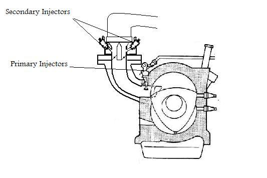
Figure 2 Fuel System Diagram (Picture modified from http://mazdarx7.iougs.com/Graphics/l...ionsystem1.jpg)
In this configuration the Primary injectors are used at idle and all of the injectors are used in boost. When driven in boost fuel leakage would occur from the throttle shafts. At idle there was no leakage because all of the fuel was injected after the throttle plate.
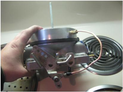
Figure 3 Original Solution Side View
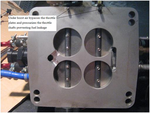
Figure 4 Original Solution Bottom View
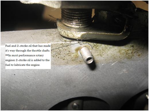
Figure 5 Picture showing the leakage after the original solution was implemented.
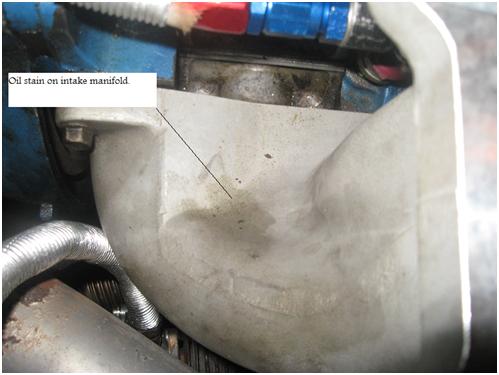
Figure 6 Original solution with oil stain on intake manifold.
Auto-nomics Throttle Body Test
Vehicle - Mazda RX7
Engine - Rotary 13BT
Engine Management - Haltech E6X
Turbo - T04E 57 trim 1AR exhaust Max Boost 15 PSI

Figure 1 Engine Bay

Figure 2 Fuel System Diagram (Picture modified from http://mazdarx7.iougs.com/Graphics/l...ionsystem1.jpg)
In this configuration the Primary injectors are used at idle and all of the injectors are used in boost. When driven in boost fuel leakage would occur from the throttle shafts. At idle there was no leakage because all of the fuel was injected after the throttle plate.

Figure 3 Original Solution Side View

Figure 4 Original Solution Bottom View

Figure 5 Picture showing the leakage after the original solution was implemented.

Figure 6 Original solution with oil stain on intake manifold.
#2
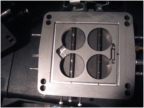
Figure 7 New machining solution to pressurize to prevent leakage
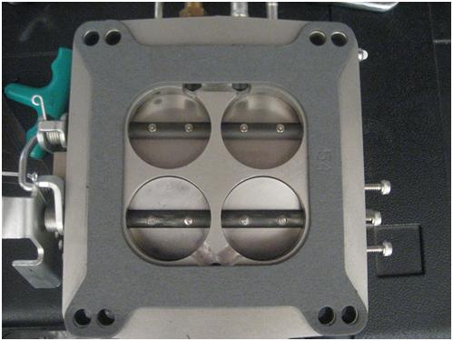
Figure 8 Picture showing gasket covering pressure passages.
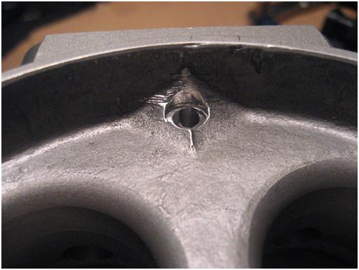
Figure 9 Inlet port that pressurizes throttle shafts.

Figure 10 Assembled throttle body. All gaskets were replaced during installation.
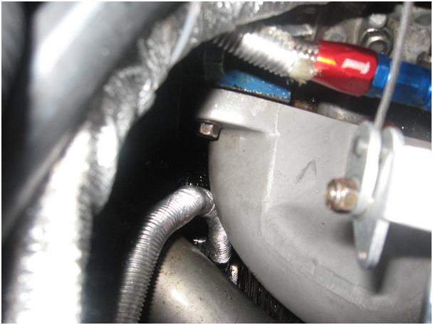
Figure 11 Pretest at 7:00 PM the intake manifold was cleaned to show any drips.
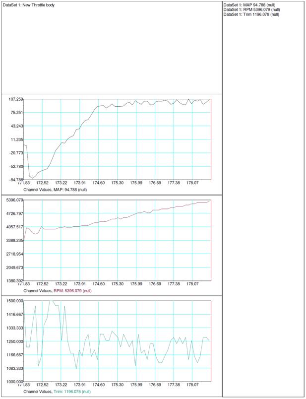
Figure 12 Snap shot of data log of test drive with new throttle body. Maximum boost pressure was 107 KPA (15.5 PSI). Trim is AFR, were 1416 equals 14.16 AFR.
#3
Continued

Figure 13 Post test at 8:15 PM the intake did not show any drips. No leakage was found during inspection.
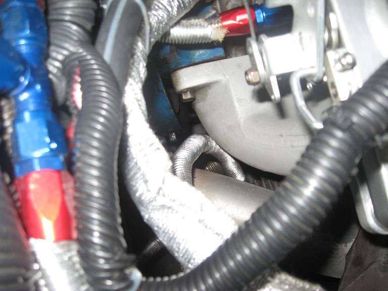
Figure 14 After day long autocross the next weekend at 131 motorsports park
#4
Test 2 UV Dye test
Auto-nomics Throttle Body UV Dye Test
UV Dye- Super Seal Engine Oil Stop Leak Kit
To verify the path of the pressure in the throttle shafts a test using UV dye was performed. There are two directions the pressure can flow in the throttle shafts. If the pressure flows to the exterior of the throttle body it is a boost leak. This prevents the fuel from leaking past the throttle shafts, but creates a small leak in the air system. If the pressure flows to the interior of the throttle body it is a throttle leak. Again this prevents a fuel leak, but can allow air to bypass the throttle plate which in theory would make the engine surge (much like a sticky blow off valve) or create idle issue. Due to the small volume of air that can travel through the throttle shafts neither surging or idle issues are likely.
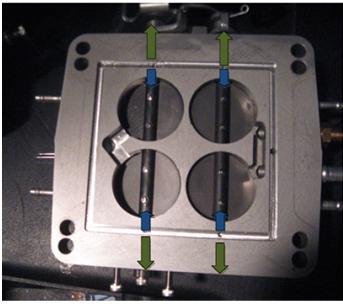
Figure 15 Paths of throttle shaft pressure, Green path shows boost leak, Blue path shows throttle leak
The UV dye was tested on an old gasket before the test. Notice only the puddles glow in the black light. For this reason the test was run in the shortest time period possible. (12:10pm-1:50PM 7/12/2009) The car was warmed up before the dye was placed in the pressure passages to insure the car was ready to boost as soon as possible.
The dye was transferred to the pressure port by means of a rubber hose with a brass fitting much like a pipette. Roughly one ounce of UV dye was used to fill the passages.
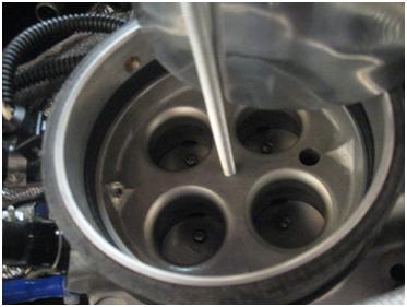
Figure 16 Pressure inlet port where the dye was pored
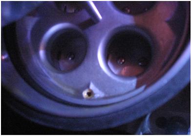
Figure 17 Pressure inlet port glowing in the black light.
After the dye was placed into the pressure inlet port the intake system was quickly put back together. The car was driven for 30 minutes on and off the highway from 12:30pm to 1:00pm on July 12, 2009. The maximum boost pressure observed was 13-14 psi. The car was accelerated in boost to a speed of 80 MPH and coasted back down to 60mph several times before returning to the garage to be disassembled for inspection. The trip was not data logged. Upon returning to the garage the initial inspection showed dye leaking from both sided of the primary shaft. The fluid could be clearly seen without the aid of the black light.
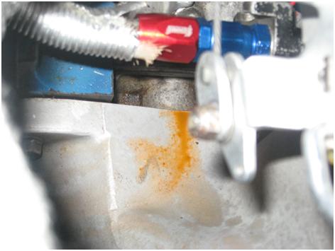
Figure 18 UV dye leaked on to rear of intake manifold
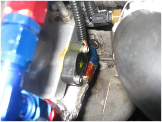
Figure 19 UV dye leaking from TPS sensor

Figure 20 Gasket showing the outline of the pressure distribution path glowing in the black light. The dye was present in all of the passages and the gasket was soaked with the dye.
So in summary the throttle modification has prevented any fuid from leaking in my application. (as long as you don't fill the throttle pressure passages with dye) To accomplish this it creates a small boost leak. The car idles fine at 1000 rpm without the aid of a IAC.
UV Dye- Super Seal Engine Oil Stop Leak Kit
To verify the path of the pressure in the throttle shafts a test using UV dye was performed. There are two directions the pressure can flow in the throttle shafts. If the pressure flows to the exterior of the throttle body it is a boost leak. This prevents the fuel from leaking past the throttle shafts, but creates a small leak in the air system. If the pressure flows to the interior of the throttle body it is a throttle leak. Again this prevents a fuel leak, but can allow air to bypass the throttle plate which in theory would make the engine surge (much like a sticky blow off valve) or create idle issue. Due to the small volume of air that can travel through the throttle shafts neither surging or idle issues are likely.

Figure 15 Paths of throttle shaft pressure, Green path shows boost leak, Blue path shows throttle leak
The UV dye was tested on an old gasket before the test. Notice only the puddles glow in the black light. For this reason the test was run in the shortest time period possible. (12:10pm-1:50PM 7/12/2009) The car was warmed up before the dye was placed in the pressure passages to insure the car was ready to boost as soon as possible.
The dye was transferred to the pressure port by means of a rubber hose with a brass fitting much like a pipette. Roughly one ounce of UV dye was used to fill the passages.

Figure 16 Pressure inlet port where the dye was pored

Figure 17 Pressure inlet port glowing in the black light.
After the dye was placed into the pressure inlet port the intake system was quickly put back together. The car was driven for 30 minutes on and off the highway from 12:30pm to 1:00pm on July 12, 2009. The maximum boost pressure observed was 13-14 psi. The car was accelerated in boost to a speed of 80 MPH and coasted back down to 60mph several times before returning to the garage to be disassembled for inspection. The trip was not data logged. Upon returning to the garage the initial inspection showed dye leaking from both sided of the primary shaft. The fluid could be clearly seen without the aid of the black light.

Figure 18 UV dye leaked on to rear of intake manifold

Figure 19 UV dye leaking from TPS sensor

Figure 20 Gasket showing the outline of the pressure distribution path glowing in the black light. The dye was present in all of the passages and the gasket was soaked with the dye.
So in summary the throttle modification has prevented any fuid from leaking in my application. (as long as you don't fill the throttle pressure passages with dye) To accomplish this it creates a small boost leak. The car idles fine at 1000 rpm without the aid of a IAC.
Trending Topics
#8
The main performance benefit is it lets you run a less restrictive intake with bigger runners, I think all aftermarket FC3s intakes use a 4150 style throttle/carb but I could be wrong. It holds 4 injectors so you can run a total of six 550 cc injectors (easy to find) instead of 2 larger secondaries, and it's a 750 cfm throttle body (I don't know what an rx7 is stock).
Maybe I should have posted in the tech section..
Here the specs on the throttle body
4 injector Throttle Body, with ported and manifold vacuum connections. 3" high, top matches 4.80" plenum, 750+ CFM. Fits Holley and Squarebore carburetor bolt patterns. Can be bored to 1000 CFM. TPS and IAC can be added with machining. Simultaneous opening blades; can be modified for progressive opening
Maybe I should have posted in the tech section..

Here the specs on the throttle body
4 injector Throttle Body, with ported and manifold vacuum connections. 3" high, top matches 4.80" plenum, 750+ CFM. Fits Holley and Squarebore carburetor bolt patterns. Can be bored to 1000 CFM. TPS and IAC can be added with machining. Simultaneous opening blades; can be modified for progressive opening
#13
#14
Since a 750 cfm rated tb can already flow more than his turbo can, there is no point in going larger. More is not better if you don't need it. In fact it's worse!
#16
glad to see someone else using this throttle body. i'm not so glad that there's a leakage problem when boosted, though. i guess i'll follow your lead if and when i run into this particular issue. however, it'll probably be long time before that happens. if you're still on here, please post it's current status with whatever others solutions you've tried.
unless he takes the car well above and beyond it's current state, this throttle body can serve him just fine. it can be ... massaged to over 1000 cfm. how far over, i have no clue, but there is at least a 1000 cfm option from the manufacturer.
unless he takes the car well above and beyond it's current state, this throttle body can serve him just fine. it can be ... massaged to over 1000 cfm. how far over, i have no clue, but there is at least a 1000 cfm option from the manufacturer.
#17
I'm still running this setup no issues. My car is down for a new clutch and diff mount now; hope to have it up before the snow sets in.
750 cfm is good to 380 hp or more so I do not think it is too small. Lots of V8 guys make big numbers on 850 holleys. Actual I want to stag my throttle because it's an off on switch after 20% throttle, I would imagine its way worse with a 1000cfm.
750 cfm is good to 380 hp or more so I do not think it is too small. Lots of V8 guys make big numbers on 850 holleys. Actual I want to stag my throttle because it's an off on switch after 20% throttle, I would imagine its way worse with a 1000cfm.
#19
Thread
Thread Starter
Forum
Replies
Last Post
Jeff20B
1st Generation Specific (1979-1985)
73
09-16-18 08:16 PM


