
Power FC Transition signal

 01-07-10, 10:42 AM
#27
EMF protection
That is likely.
Re. sketch below taken from here http://www.kpsec.freeuk.com/components/relay.htm

This shows a relay switched by a transistor. You can imagine replacing the realy with any of the solenoids. The connection solenoid / transistor are the pins of the ECU. Each pin can be controlled by individual transistors. The "input" to each transistor (on/off switch) is generated by the ECU logic.
Rather than "hugging" each individual solenoid with individual commutating diodes, It may be very possible that a few common diodes are installed inside the PFC "shorting" all the pins to the PFC common 12V power supply and dissipate the EMFs.
Just speculating... It would be nice to have a schematic of the PFC inside and then play safe... Does anyone have it? I guess a schematic of the stock ECU would be just fine...
- Sandro
Re. sketch below taken from here http://www.kpsec.freeuk.com/components/relay.htm
This shows a relay switched by a transistor. You can imagine replacing the realy with any of the solenoids. The connection solenoid / transistor are the pins of the ECU. Each pin can be controlled by individual transistors. The "input" to each transistor (on/off switch) is generated by the ECU logic.
Rather than "hugging" each individual solenoid with individual commutating diodes, It may be very possible that a few common diodes are installed inside the PFC "shorting" all the pins to the PFC common 12V power supply and dissipate the EMFs.
Just speculating... It would be nice to have a schematic of the PFC inside and then play safe... Does anyone have it? I guess a schematic of the stock ECU would be just fine...
- Sandro
01-08-10, 12:10 PM
#28
I think you might have it reversed.
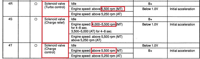
The CCN is grounded before transition, the TCN is not. The CCN is grounded because engine vacuum is supplied to the actuator to keep it shut. After transition, the solenoid is disengaged (12V now) and you have pressure applied to both sides of the charge control actuator. The mechanical design of the actuator and the plumbing is such that the valve will open. You can just use pin 4R (TCN) instead. It's just driving a relay, I personally wouldn't worry about using it.
The CCN is grounded before transition, the TCN is not. The CCN is grounded because engine vacuum is supplied to the actuator to keep it shut. After transition, the solenoid is disengaged (12V now) and you have pressure applied to both sides of the charge control actuator. The mechanical design of the actuator and the plumbing is such that the valve will open. You can just use pin 4R (TCN) instead. It's just driving a relay, I personally wouldn't worry about using it.
01-08-10, 01:23 PM
#29
Yes, thanks, that is what I meant.
But I realized I mistakenly inverted the values under column 86. They should read instead <1V Before Transition (same as PIN 4T because the PFC does keep it grounded) and 12V after transition (relay de-energized because the transistor/switch driving the PIN 4T is opened by the PFC - at least this is my hypothesis, I realize you may have a different opinion on how it works).
My concerns may be unjustified, but given that I don't know for sure the design parameters of the PFC, my current thinking is indeed to use 4R (TCN) but with a solid state relay (SSR) driving the WI solenoid, rather than a mechanical relay. The benefits are (i) that the input impedance of the SSR is very high, so that the additional current flowing through the PFC transistor driving the PIN 4R is negligible, and (ii) that there is no inductive reverse polarity issue to worry about - whether the PFC is already protected or not against it. This is what the circuit will look like

There are still a couple of issues though:
- The SSR requires <1V to disengage; that should probably work with the PFC when the transistor driving PIN 4R is switched off (RPM drops back below 3,000 RPM or whatever set-up I have in my PFC), the FSM says <1V (I guess because even if the transition is turned off, its impedance will still be finite and a small current will still flow across it); this is something I will measure; if necessary I will add a resistor in series to the SSR input.
- Second, Omega indicates at page 5 their manual http://www.omega.com/Manuals/manualpdf/M3323.pdf that a commutating diode must be installed across any inductive load on the power side of their SSR, and I confirmed with them that this is the case even with a modest load such as the WI solenoid I have (50 Ohm and 12V). The diode is not yet shown in the circuit above.
Again, all this may be overkill but (i) I like to play safe and not damage equipment, and (ii) this is my playground (not my daily job) and I enjoy doing these things, as you know already...
- Sandro
But I realized I mistakenly inverted the values under column 86. They should read instead <1V Before Transition (same as PIN 4T because the PFC does keep it grounded) and 12V after transition (relay de-energized because the transistor/switch driving the PIN 4T is opened by the PFC - at least this is my hypothesis, I realize you may have a different opinion on how it works).
My concerns may be unjustified, but given that I don't know for sure the design parameters of the PFC, my current thinking is indeed to use 4R (TCN) but with a solid state relay (SSR) driving the WI solenoid, rather than a mechanical relay. The benefits are (i) that the input impedance of the SSR is very high, so that the additional current flowing through the PFC transistor driving the PIN 4R is negligible, and (ii) that there is no inductive reverse polarity issue to worry about - whether the PFC is already protected or not against it. This is what the circuit will look like
There are still a couple of issues though:
- The SSR requires <1V to disengage; that should probably work with the PFC when the transistor driving PIN 4R is switched off (RPM drops back below 3,000 RPM or whatever set-up I have in my PFC), the FSM says <1V (I guess because even if the transition is turned off, its impedance will still be finite and a small current will still flow across it); this is something I will measure; if necessary I will add a resistor in series to the SSR input.
- Second, Omega indicates at page 5 their manual http://www.omega.com/Manuals/manualpdf/M3323.pdf that a commutating diode must be installed across any inductive load on the power side of their SSR, and I confirmed with them that this is the case even with a modest load such as the WI solenoid I have (50 Ohm and 12V). The diode is not yet shown in the circuit above.
Again, all this may be overkill but (i) I like to play safe and not damage equipment, and (ii) this is my playground (not my daily job) and I enjoy doing these things, as you know already...
- Sandro
01-23-10, 06:21 PM
#30
I tested the release of the Omega SSR today, and just wanted to share the results.

The voltage release was 3.7V well above the 1V indicated in the data sheet. So, it will work with no need to put any additional resistance in series. The switching delay on release is "noticeable", like the 50-100 msec indicated earlier. This is not a problem for my application.
- Sandro
The voltage release was 3.7V well above the 1V indicated in the data sheet. So, it will work with no need to put any additional resistance in series. The switching delay on release is "noticeable", like the 50-100 msec indicated earlier. This is not a problem for my application.
- Sandro
01-23-10, 08:21 PM
#31
Rotary Enthusiast
I donno,, to complicated,, i like the dudemanns simple set up.
this has been talked before, just what IF, some small component stops water at 20+ psi boost on 93 pump??
it could lead to a lot of money.
KISS,
this has been talked before, just what IF, some small component stops water at 20+ psi boost on 93 pump??
it could lead to a lot of money.
KISS,

Thread
Thread Starter
Forum
Replies
Last Post
Turblown
Vendor Classifieds
12
10-17-20 03:25 PM
10, column, commutating, diodes, emf, foto, low, power, protection, rele, signals, solenoid, solenoids, transistor, transition