
Power FC Transition signal
 01-01-10, 11:13 AM
#1
Transition signal
Happy 2010 to everyone!
I am planning on testing pre-compressor WI on my stock twin-turbos
I need a signal to open a solenoid valve and inject atomized water to the secondary compressor but only after transition
The valve (Coolingmist) is closed when the solenoid is de-energized and open when the solenoid is energized (12V)
Solenoid impedance is 22.4 ohm
I was thinking of grounding the solenoid trough the PFC, either to pin 4R (turbo control) or to pin 4T (charge control)
Questions:
1. I read here https://www.rx7club.com/showthread.p...light=solenoid that the OE solenoid valves impedance is 40 ohm. So, when the solenoid are grounded through the PFC pins, these pins normally flow around 14 V/40 ohm = 0.35 amp. But if I add the 22.4 ohm solenoid in parallel, pin will have to flow close to 1 amp. Would the PFC be able to handle it? I read in the other threads about injectors that 2 amp is considered safe, but don't know if this can be generalized to these other pins as well.
2. I am a little confused as of the energization status of the turbo control and charge control solenoids. Section F of the FSM seems to indicate that 4R sees battery voltage before transition while 4T sees battery voltage after transition. I believe this means that I should use the 4R connection (not the 4T) if I want my Coolingmist solenoid valve to be energized after transition. Is my understanding/conclusion correct?
Thanks,
Sandro
 01-01-10, 12:25 PM
#2
1. Personally, I wouldn't push the driver current more than 1 amp.
2. Disclaimer: I might be totally off but from what I can tell, 4R activates the turbo control which controls the flapper gate in the exhaust to spool the 2nd turbine. Once this happens, the charge control (4T) flapper in the y-pipe needs to be opened when the 2nd turbo is expected to provide boost.
--Edit--
You may be able to monitor this behavior in the PFC sensor/switch screen.
Last edited by NeoTuri; 01-01-10 at 12:29 PM.
01-01-10, 02:32 PM
#3
I've already thought about what you are proposing somewhat. Take a look at this log I put in my sequential turbos demystified thread:

On the top graph, the BLUE line is the charge control solenoid trigger, pin 4T (sensor/sw CCN under monitor window). It is ON (grounded) until the turbo transition rpm is reached. The GREEN line is the turbo control solenoid trigger (sensor/sw TCN) pin 4R. This actually triggers both the vacuum and pressure solenoids. Remember that those are not duty controlled solenoids, they're just switched on and off.
Here is the relevant FSM stuff:
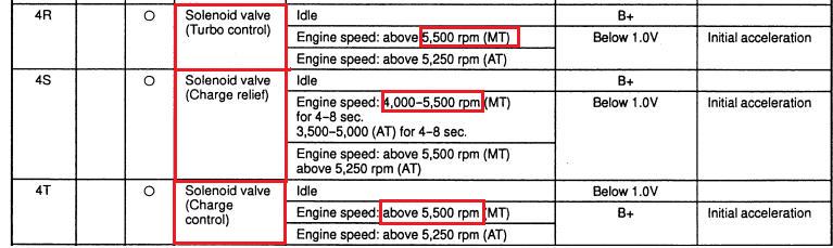

But here's the deal. From what I've seen of various PFC logs, if you coast after the transition RPM, the solenoids will still stay in their normal after-transition modes. What I mean by this is, you will need a Hobbs switch or some other trigger to keep the PFC from running your water injection when you are out of boost but over the transition RPM. Go out and log "TCN" and "CCN" for yourself. "1" means energized/grounded, "0" means off.
The simplest way to do it would be to wire a Hobbs switch in-line with the trigger produced by PFC pin 4R (turbo control). Run that to negative side of the coil in your water injection relay (pin 85 or 86). Or instead of a Hobb switch, you could trigger it off pressure sensor voltage using a voltage switch: http://www.autospeed.com.au/cms/A_110548/article.html which can be bought here http://store.autospeed.com/Items/22876 . That way you don't have to worry about what pressure a Hobbs switch is seeing compared to what the MAP sensor is reading.
You could even wire the A/I relay to the exhaust overheat pin on the ECU so that you could log EXACTLY when the A/I relay is engaged. That is Sensor/Sw HWL in the PFC and I believe PFC pin 2I.
Also, if you are doing a bunch of wiring down by the ECU I highly recommend you pick up one of these extension harnesses: http://www.boomslang.us/extension.htm Banzai Racing also sells one. The wires are all 18 gauge (easier to work with than the factory FD wires) and don't have to worry about hacking up your harness.
On the top graph, the BLUE line is the charge control solenoid trigger, pin 4T (sensor/sw CCN under monitor window). It is ON (grounded) until the turbo transition rpm is reached. The GREEN line is the turbo control solenoid trigger (sensor/sw TCN) pin 4R. This actually triggers both the vacuum and pressure solenoids. Remember that those are not duty controlled solenoids, they're just switched on and off.
Here is the relevant FSM stuff:
But here's the deal. From what I've seen of various PFC logs, if you coast after the transition RPM, the solenoids will still stay in their normal after-transition modes. What I mean by this is, you will need a Hobbs switch or some other trigger to keep the PFC from running your water injection when you are out of boost but over the transition RPM. Go out and log "TCN" and "CCN" for yourself. "1" means energized/grounded, "0" means off.
The simplest way to do it would be to wire a Hobbs switch in-line with the trigger produced by PFC pin 4R (turbo control). Run that to negative side of the coil in your water injection relay (pin 85 or 86). Or instead of a Hobb switch, you could trigger it off pressure sensor voltage using a voltage switch: http://www.autospeed.com.au/cms/A_110548/article.html which can be bought here http://store.autospeed.com/Items/22876 . That way you don't have to worry about what pressure a Hobbs switch is seeing compared to what the MAP sensor is reading.
You could even wire the A/I relay to the exhaust overheat pin on the ECU so that you could log EXACTLY when the A/I relay is engaged. That is Sensor/Sw HWL in the PFC and I believe PFC pin 2I.
Also, if you are doing a bunch of wiring down by the ECU I highly recommend you pick up one of these extension harnesses: http://www.boomslang.us/extension.htm Banzai Racing also sells one. The wires are all 18 gauge (easier to work with than the factory FD wires) and don't have to worry about hacking up your harness.
01-01-10, 03:07 PM
#4
Thanks Raymond.
In my first post I did not describe in its entirely the WI configuration I have in mind.
The water pump will be activated by a pressure switch (say 7 psi). That should take care of the "coasting" conditions.
I will have two separate atomizing nozzles, one for each compressor.
I wanted to avoid injecting water to the second compressor when not working; that is why I thought of using a "transition" signal for that, either the CCN or the TCN (in Datalogit language) which are complementary.
Now though, I realize there are actually two separate solenoids to control the Turbo Control valve driven by the same pin 4R.
Which means the pin 4R already "sees" 0.70 amp (assuming the impedance of each of the TC solenoids is 40 ohm)
Adding in parallel another 22.4 ohm (Coolingmist valve solenoid) would raise the current to 1.325, not 1 amp as I had previously stated.
So the question is, could the PFC handle that? or, should I think of something else?
NeoTuri indicated he would avoid that [thanks for your reply], but I have seen numerous other threads stating that the injectors could "safely" been driven by the PFC up to 2 amp.
- Sandro
01-01-10, 03:26 PM
#5
The simplest way to do it would be to wire a Hobbs switch in-line with the trigger produced by PFC pin 4R (turbo control). Run that to negative side of the coil in your water injection relay (pin 85 or 86). Or instead of a Hobb switch, you could trigger it off pressure sensor voltage using a voltage switch: http://www.autospeed.com.au/cms/A_110548/article.html which can be bought here http://store.autospeed.com/Items/22876 . That way you don't have to worry about what pressure a Hobbs switch is seeing compared to what the MAP sensor is reading.
You could even wire the A/I relay to the exhaust overheat pin on the ECU so that you could log EXACTLY when the A/I relay is engaged. That is Sensor/Sw HWL in the PFC and I believe PFC pin 2I.
Also, if you are doing a bunch of wiring down by the ECU I highly recommend you pick up one of these extension harnesses: http://www.boomslang.us/extension.htm Banzai Racing also sells one. The wires are all 18 gauge (easier to work with than the factory FD wires) and don't have to worry about hacking up your harness.
- The voltage switch could perhaps be used (assuming the impedance of such switch is high enough) to "relieve the pin 4R from the duty of driving the Coolingmist solenoid directly - I could interpose a relay for that, if 1.33 amp is too much for the PFC.
- For now, my objective is to evaluate the effectiveness of evaporative cooling in the compressors, using the overheating signal may not be adequate
- Yes, I already have installed a similar harness extension
- Sandro
01-01-10, 03:54 PM
#6
NeoTuri indicated he would avoid that [thanks for your reply], but I have seen numerous other threads stating that the injectors could "safely" been driven by the PFC up to 2 amp.
BUT you can just drive the secondary nozzle off the CCN if you wire up the relay right. Basically you connect pin 86 to the CCN output and the pin 85 to ground. Before transition, CCN output is GND to relay pin 86. The coil in the relay would not have power and ground to complete the circuit and engage the A/I. After transition, CCN output is +12V. +12V on pin 86 will activate the relay. It's not a big deal at all, especially if you were already going to run a separate relay for the second A/I stage. You can always wire a single Hobb switch or voltage switch so that it can provide the pressure based trigger for both stages of the A/I.
Now can you post some more details about how you had planned to wire up the second stage?
- For now, my objective is to evaluate the effectiveness of evaporative cooling in the compressors, using the overheating signal may not be adequate
I'll see if I can get a mod to move this thread to the A/I section and rename it to be more descriptive.
01-01-10, 04:11 PM
#7
I am by no means saying that the PFC can't handle more than 1 amp drain on the driver circuits. I am assuming that the solenoid circuity is similar to the injector hardware (it wouldn't be TOO difficult to crack it open to find out, just tedious).
Trending Topics
01-01-10, 05:23 PM
#8
Sorry, I misunderstood. I am still behind in my learning curve.
But now, I am still confused. Let me try to explain what I still do not understand.
1. When you say CNN signal, where can I get this signal from? Is it the voltage at 4T?
2. If so, by looking at the test condition table, it says above xxxx rpm (i.e. after transition), V=battery voltage. I guess after transition the transistor inside the PFC disconnects the pin 4T from the ground, causing the circuit of the CC solenoid to open. With no more current flowing through the CC solenoid, the voltage across the solenoid (including the 4T pin) becomes the battery voltage.
3. Now, if I "take" that voltage and connect it to pin 86 of the relay, current shall be flowing through the relay coil to operate the relay, and therefore also through the CC solenoid. To avoid triggering the CC solenoid, I would have to use a relay with a very high impedance, flowing ? microamps ? in its coil (to avoid activating the CC solenoid) and still capable of triggering its own power circuit. Probably a power transistor like the ones in the PFC. Any idea on how to implement this?
Will defer the discussion on AI to another thread when I will have more to share. Right now I am focusing on water atomization (I have been posting about the Bete PJ nozzles already). Next, I will have to figure how to measure and log Temp post compressor and pre-IC. I am not planning on any 2nd stage injection right now. Just a plain vanilla Coolingmist system pressure signal operated, with two Bete PJ nozzles, and the logic being discussed here to avoid sending water to a non-operating secondary turbo, while the pump is running.
- Sandro
01-01-10, 06:19 PM
#10
Mmmm, cool stuff at that AutoSpeed website
In particular, they have this solid state relay (SSR) http://store.autospeed.com/Items/187...DC%20Switching
Input impedance is 1.2 kOhm
That should work with the 4R pin (Turbo Control)
This SSR should only add 12 mAmp (14 V / 1,200 Ohm) over the 700 mAmp currently flowing through the pin, when grounded.
What do you think?
- Sandro
01-01-10, 06:27 PM
#11
Something that's high impedance or a 3-way relay in which the CCN solenoid is on the normally-off terminal and your solenoid is on the normally-ON terminal. That way, you can decide how the solenoids are powered.
My awesome MS Paint skillz...

Does something like this interest you?
My awesome MS Paint skillz...
Does something like this interest you?
Last edited by NeoTuri; 01-01-10 at 06:57 PM.
01-01-10, 08:09 PM
#13
Something that's high impedance or a 3-way relay in which the CCN solenoid is on the normally-off terminal and your solenoid is on the normally-ON terminal. That way, you can decide how the solenoids are powered.
My awesome MS Paint skillz...
Does something like this interest you?
My awesome MS Paint skillz...
Does something like this interest you?
But in this case, the triggering coil would be in series to the CCN solenoid. I would need a relay with a very low impedance to make sure the CCN solenoid would stay energized before the transition. CCN solenoid impedance is 40 Ohm I believe. I wouldn't go above 5 Ohm. Do you know of any relay like that?
- Sandro
01-02-10, 12:27 AM
#14
Oh no, the new relay replaces the CCN solenoid. Activating it will allow the CCN solenoid down below to be powered by the +12v source. When it is off, it applies +12v power to the other circuit where the other solenoid will be.
The CCN box up top is actually 4T.
The CCN box up top is actually 4T.
01-02-10, 02:52 AM
#15
Originally Posted by Sandro
2. If so, by looking at the test condition table, it says above xxxx rpm (i.e. after transition), V=battery voltage. I guess after transition the transistor inside the PFC disconnects the pin 4T from the ground, causing the circuit of the CC solenoid to open. With no more current flowing through the CC solenoid, the voltage across the solenoid (including the 4T pin) becomes the battery voltage.
3. Now, if I "take" that voltage and connect it to pin 86 of the relay, current shall be flowing through the relay coil to operate the relay, and therefore also through the CC solenoid. To avoid triggering the CC solenoid, I would have to use a relay with a very high impedance, flowing ? microamps ? in its coil (to avoid activating the CC solenoid) and still capable of triggering its own power circuit. Probably a power transistor like the ones in the PFC. Any idea on how to implement this?
3. Now, if I "take" that voltage and connect it to pin 86 of the relay, current shall be flowing through the relay coil to operate the relay, and therefore also through the CC solenoid. To avoid triggering the CC solenoid, I would have to use a relay with a very high impedance, flowing ? microamps ? in its coil (to avoid activating the CC solenoid) and still capable of triggering its own power circuit. Probably a power transistor like the ones in the PFC. Any idea on how to implement this?
The whole thing is a lot like the fan relay trigger from the PFC. When the fans are OFF, +12V comes out of pin 3D. When the fans are switched ON, a ground signal comes out of pin 3D. I have used the PFC fan relay trigger on two different custom fan setups so I'm familiar with how the PFC does this kind of thing.
01-02-10, 05:51 AM
#16
I do not think it's that simple.
The pins get their voltage through the solenoids not by the PFC on its own.
Re. the wiring diagram and the condition table you copied in your post #3 above.
Let's look at the CCN for instance.
At one end, the solenoid is powered through the EGI (12 V nominal)
At the other end, the CCN is grounded through the PFC
Inside the PFC there must be a transistor wired as a switch, between the pin 4T and the ground.
Re. condition table, note that at "idle" (before transition) V is below 1V, not 0V. In this condition the transistor/switch is closed by the PFC logic. CCN is energized. Current flows through the circuit. The transistor has its own finite resistance. The amount of current is determined by the resistance of the CNN plus the resistance of the transistor in its closed position. The voltage at 4T (<1V) is determined by that current time the resistance of the transistor.
Conversely, after transition, the V at 4T is 12 V. This is because the transistor/switch is open (infinite resistance). No current flows through CNN, therefore the V at 4T is the same battery voltage.
If there were no CNN connected, the pin would never get powered, and its V would always be zero. The PFC on its own does not "deliver" voltages to the pin.
That is why I am concerned about placing anything in between. If the overall resistance is reduced too much (e.g. adding a solenoid in parallel) the current could become too high and damage the transistor when closed.
By the way, it must be the same for 3D as well. Note it never goes to 0V either, but just below 1V.
- Sandro
01-02-10, 06:50 AM
#17
I see it now... interesting
So, let me repeat to make sure I understand it right. The new relay gets triggered by the PFC (top box on the left = 4T "switch"). When 4T is closed (before transition) CCN gets powered by a 12 V source and connected directly to the ground - no more through the 4T "switch".
I guess it should work. Obviously, the resistance of the triggering circuit (the one going to 4T) should be no less than the 40 Ohm of the CCN solenoid, to avoid damaging the PFC transistor.
- Sandro
01-02-10, 12:42 PM
#22
Ssr
I have also looked at these SSRs. Found this in particular.
http://www.omega.com/Temperature/pdf/SSRDC100V.pdf
There is always a 1V to deal with - V has to go below 1V to release it... interesting stuff
http://www.omega.com/Temperature/pdf/SSRDC100V.pdf
There is always a 1V to deal with - V has to go below 1V to release it... interesting stuff
01-04-10, 04:03 PM
#24
SSR - more info
Just wanted to share some more info about the Omega SSR, not reported in their data sheet http://www.omega.com/Temperature/pdf/SSRDC100V.pdf
Had an exchange of emails with Rick Dole, application engineer at Omega and got the following clarifications.
1. Input impedance is 2K ohm nominal
2. If you add resistance (approx 2K ohm) the release voltage will be cut by a factor of 2 [takes care about the <1V uncertainty...]
3. Switching cycle is 50 to 100 msec [for those planning on piggy-backing the the fuel injectors signal to drive water injectors...]
- Sandro
01-07-10, 09:03 AM
#25
EMF protection
Question: Wouldn't this apply for all the solenoids switched by the PFC?
- Sandro