Rats Nest Guide Part 2
#1
Junior Member
Thread Starter
Rats Nest Guide Part 2
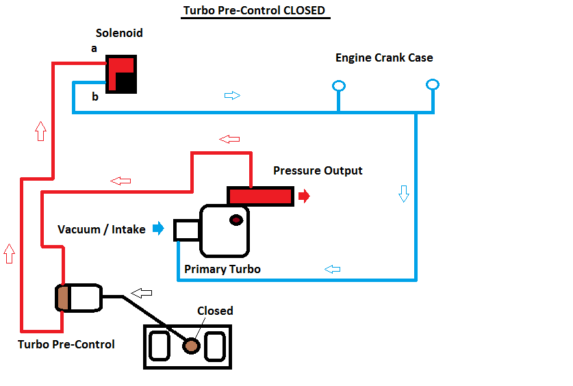
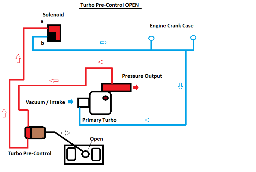
In the next diagram you can see the opposite, as the car hits 3.5k RPM the second turbo is spooled up and this is achieved when the solenoid is closed causing the pressure from the primary turbo to bleed back to the actuator forcing the actuator open which will spool up the second turbo.
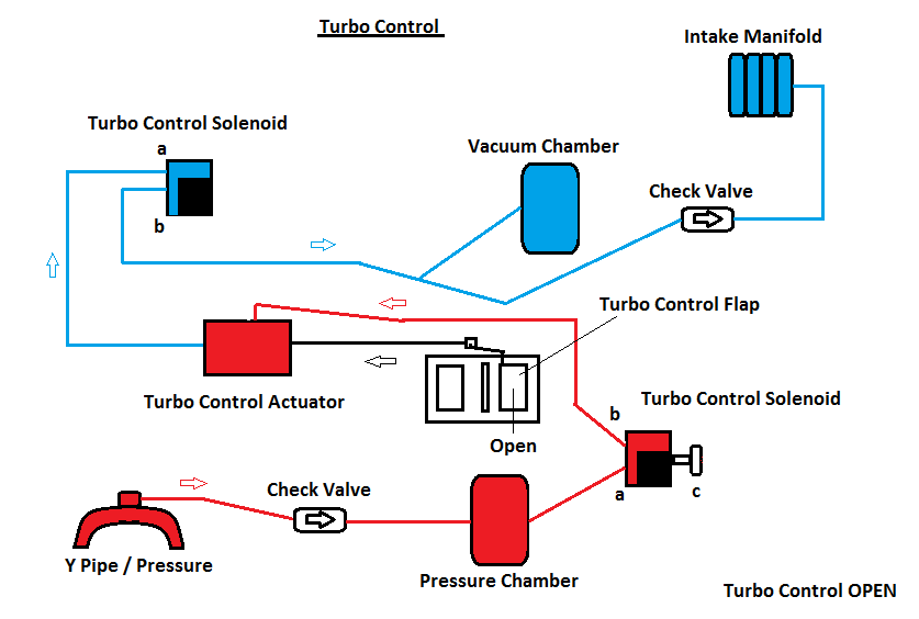
Turbo Control...
Now the second turbo has spooled to match the primary we need both turbos to be fully engaged to work together, this is achieved using the turbo control actuator and this uses two solenoids to do the job, one for vacuum and one for pressure. The pressure source is from a pipe that come from the Y PIPE and connects to the pressure chamber, the vacuum source is from the vacuum tank / manifold and when the turbo control isn't required the turbo control solenoid for vacuum is closed and the pressure solenoid is vented from B to C see below:
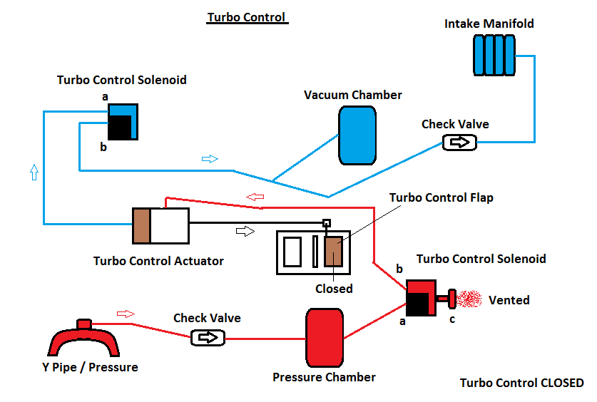
however when it is needed the pressure solenoid switches allowing pressure to flow from A to B which forces the piston to close and the vacuum solenoid open allowing vacuum from A to B fed from the vacuum tank and manifold to pull the piston opening the flap in the exhaust system.
The wastegate control is done in the same manor as the pre-control as you can see below:
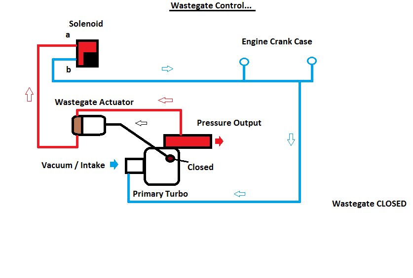
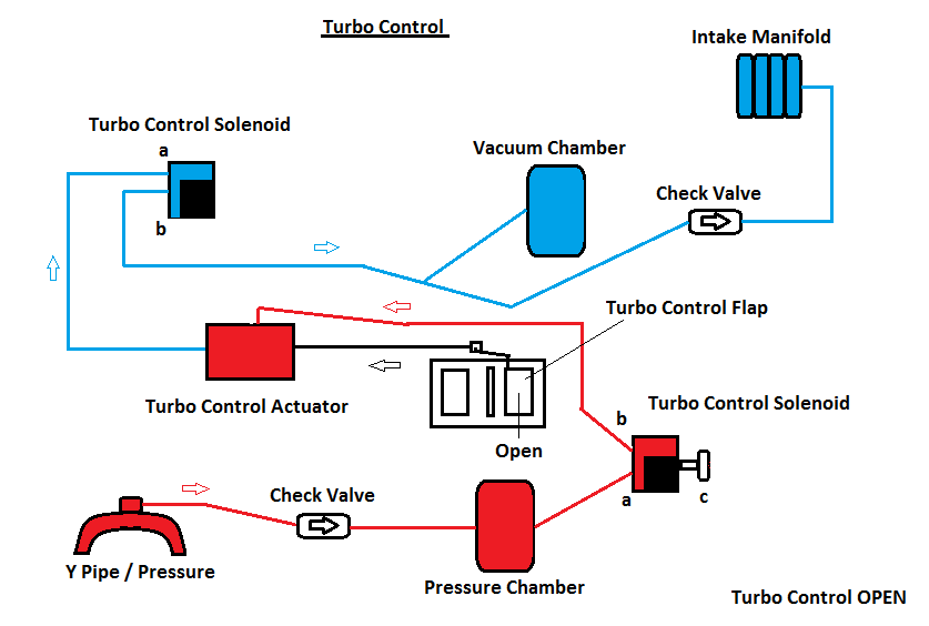
now that we can see how the system works and what controlls it we need to be able to diagnose it.
To do this we need to check all the solenoids in the rack to see if they are working correctly.
As stated above they each have 3 ports or 2 ports, the 2 ports act as a switch allowing vacuum / pressure to flow through or not and the 3 ports have a bleed off port, this is so the actuators can reset or return to there previous state and this can only be done if the vacuum or pressure holding them closed / open is released.
So how to check the solenoids...
We need to warm an oven up to 120 degrees centigrade to simulate engine heat, believe me i did this on a cold test and they worked fine, i did the same test on a hot test and a few failed !!!.
First, the resistance test:
Use your multimeter and test the resistance across the terminals. It should be about 40ohms, or a little more if the solenoid is hot. If it shows a resistance above 60 or below 30ohms, junk it.
When the solenoid is powered off check that there is flow between C and B.
Then check with vacuum port A and check for leaks, there should be none, then apply 15PSI and check again for leaks...
Now energise the solenoid and check that C is closed and flow between A & B is true, then check if there is vacuum & pressure with no leaks on C.
Repeat the test after the actuator has been heated. if the actuator doesn't move bang it to free the plunger, however this means its damaged and failing under heat, if the solenoid fails any of these test bin it and replace !!!!, now its worth mentioning you can buy the original factory solenoids or buy a MAC 3 port one which will do exactly the same at a fraction of the price and last longer !!!!.
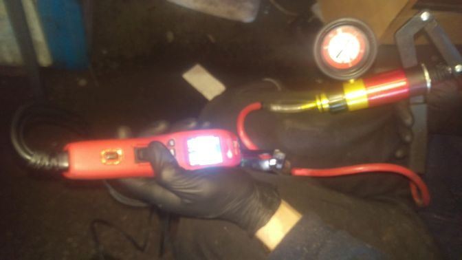
You don't need an expensive probe to actuate the solenoid just a 12v source from a battery !!!
Right providing the actuators are working well you need to check the vacuum lines to make sure they are connected to the correct ports to function correctly, they say a picture speaks a 1000 words well in this case it does unless you have the original FSM in which case it took me 3 weeks to fully decifer it and make a diagram that actually makes sense .
break down of the actuators :
Turbo Control – CLOSED then opened when needed
Wastegate & Pre-Control – Closed then opened when needed
Charge Relief – Open then closed when charge control is closed
Charge Control – Closed then open when needed
Double Throttle Control – Closed then opened when needed
You should be able to see that all solenoids are connected to actuators on port B and port A is the Vacuum or pressure source, and if it has it Port C is the dump source, follow the key here and you should be fine !!!
The key for the vacuum diagram is as follows:
A = Solenoid valve – Pressure Regulator Control (Fuel pressure)
B = Solenoid valve – Relief 1 (AWS System Secondary Air Control Pump)
C = Solenoid valve – Switching (AWS)
D = Solenoid valve – (EGR)
E = Solenoid valve – Turbo Control (2nd turbo actuator flap)
F = Solenoid valve – Charge Control (2nd turbo Y Pipe flap open / close)
G = Solenoid valve – Double Throttle Control
H = Solenoid valve – Charge Relief (BOV for second turbo)
I = Solenoid valve – Wastegate Control
J = Solenoid valve – Turbo Pre Control
Colours for the piping and connections:
A = Orange – Pressure Regulator Control
E = Blue – Turbo Control
F = Green – Charge Control
G = Red – Double Throttle Control
H = Yellow – Charge Relif
J = Pink –Turbo Pre Control
I = Green – Wastegate Control

Right now for my edited diagrams that should make more sense !!!
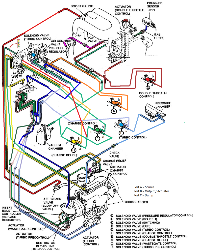
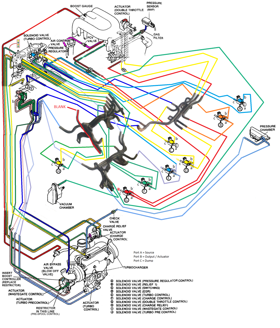
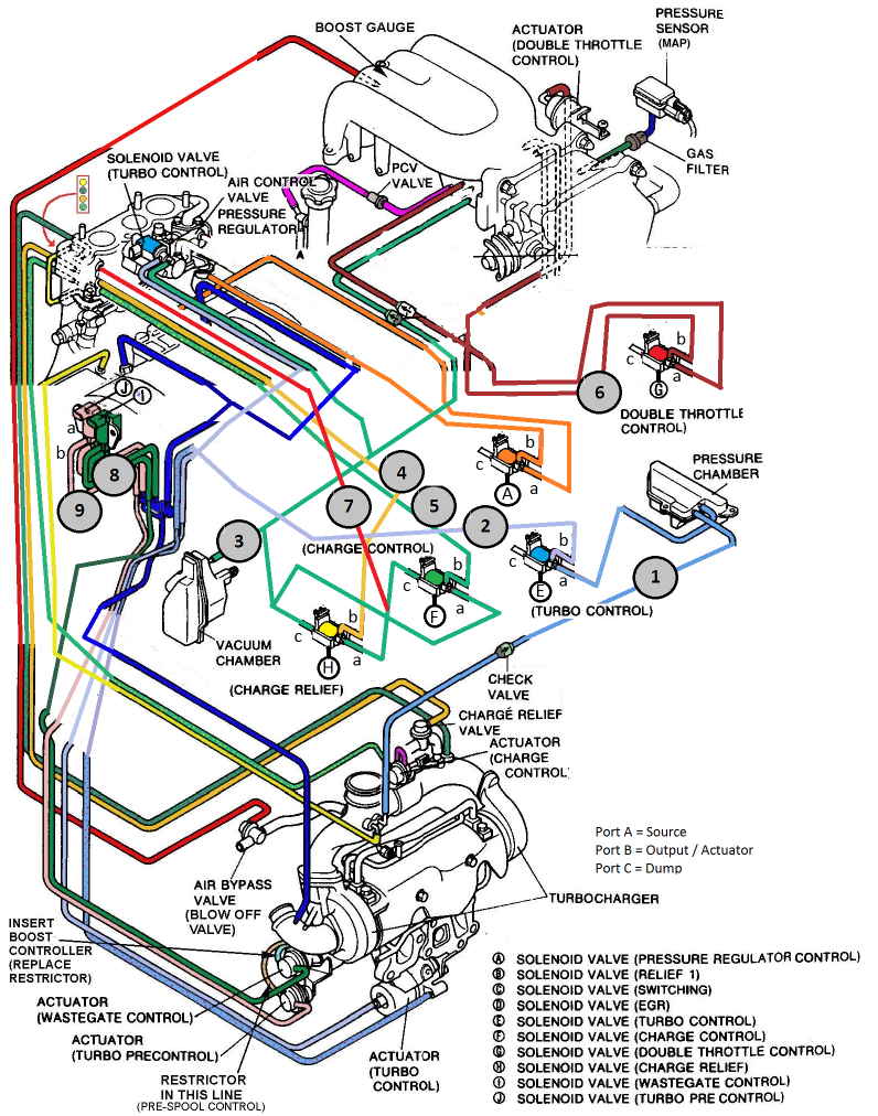
Trouble Shooting Actuators: (Attatch boost guage at numbered location)
First thing to check before anything is the solenoids for sticky plungers and leaking as above and to check the Actuators for leaks and smooth movements.
After this you need to check the vacuum and pressure tanks without these you will have boost problems.
Assuming you have no boost leasks and all your actuators are working correctly you need to check for broken or missing pipes in the rats nest. The diagram above is for a relocated rats nest and so diagnostics is easier to do as you can get to all the lines however you can T off the lines in various places without removing the manifold to test for issues.
How the turbo system should work..
Initially the primary turbo will be the only source of pressure and the manifold will be the only source of vacuum excluding the fact the presure and vacuum tanks which will hold the two forces needed. The primary turbo feeds the Pre-Control actuator and wastegates vacuum and pressure forces required to operate where as the charge relief and control actuators and solenoids use the manifold via the vacuum tank to obtain vacuum and the Y Pipe to feed the positive pressure required for both of these to work without the use of the Pressure tank. The Turbo control actuator is the only solenoid to use the pressure tank for operation.
So picture this, the car is accelerating from the stop possition, the wastegate, pre-control, charge relief and charge control are the areas to look at during the primary turbos boost condition. From stand still to 3k RPM the pre-control solenoid will be closed along with the wastegate providing overboost condition isnt true, the charge control flap will be closed and the charge relief will also be closed. When the car is transitioning to the second turbo around the 3-3.5k RPM the pre-control solenoid will start to open bleeding exhaust gases to the secondary turbo, whilst this turbo is spooling a slight pressure drop will occur on the primary turbo, the charge relief valve will also slightly open when the pressure on the second turbo spikes or spools too quickly as both turbos need to be running at the same speeds and pressure to prevent them fighting each other when they both suppliy boost, when pressure equilises the charge relief will start to close and the charge control will start to open allowing both turbos to meet and provide boost, at the same time the turbo control solenoid will also be opening and when both turbos match the turbo control flap will open fully and both turbos will function together.
If you find there is a problem here then find out where the problem occurs and check the following bearing in mind with out meeting the target boost of 10 psi on the primary turbo the second will not start to transition, like wise when the second turbo engages it will need to see 8 psi of pressure to match the now targeted pressure of 8 psi from the primary as the dip which is casued from suppliying the 2nd turbo has to be accounted for, once they meet they should rise together to meet 10 psi again and taper off to 8 psi up to redline.
Trouble shooting checklist, cross reference with the numbered grey circles on the diagram this is where you T the second boost guage to fault find.
1. Pressure chamber, the pressure chamber is used for the 2nd turbo control flap that engages the second turbo and isnt used for anything else, You should get boost pressure here and hold at the peak PSI of the cars capabilitys, minimum 10 PSI . once obtained it should never waver or leak down. If there is no pressure here or it doesnt match what the primary turbos boost levels reach something is wrong with the feed to the pressure tank which is fed off the y pipe, check for leaks!
2. Turbo Control Actuator for the 2nd turbo engagement, here you should see 0 PSI until the change over (3-4k RPM) when the second turbo is engaged, during pre spool you should see the pressure increase then hold. Once you throttle down and the RPMS drop below the pre controls parametres ( Under 3k RPM ) the boost guage will drop back to 0 PSI, if this does not happen check for leask from the actuator to the solenoid or for a sticky or non functioning solenoid
3. This is the cars main vacuum storage, like the pressure tank in number 2 you should see a negative vaccum number and this once obtained shouldnt waver or leak down. If you dont see this then check your check valves and lines between it and the manifold, also the other solenoids that share the vacuum line also need to be checked for leaks.
4. Charge Relief, here you should see no vacuum when the second turbo is disengaged, once the turbo is spooling a steady rise in negative vacuum should bee seen and the BOV will open, once spooled down the BOV will close again and 0 vaccum will be seen. So if you do not see this check to see if lines have come off or the solenoids are working correctly, also if the actuators are not working or stuck this will casue the system to fail.
5. Charge Control – here you should see vacuum when the second turbo isnt ready to engage and then positive boost when the flap is open and the second turbo is engaged, when the second turbo is disengaged the guage should show vacuum.
6. Double Throttle Control, here vacuum is applied during the warmup process, here you should see a minus vacuum number and once the car has warmed up slowly returning to 0 PSI as the vacuum has blead off and the extra throttle plenums will open. If there is a problem here check you lines and check control valve and actuators.
7. Charge Relief & Charge Control share a common pressure line to flip states, you should see this rise from 0 PSI to the cars maximum capabilities minimum of 10 PSI. This will occur when the second turbo is engaged and drop back to 0 once you throttle down.
8. Wastegate, here a negative vacuum number will be see until the wastegate is needed, then a positive pressure should be seen when activated.
9. Turbo Pre-Control, here a negative vacuum number will be see until the Turbo Pre-Control is needed, then a positive pressure should be seen when activated.
And here is the ECU pinout for the solenoids electrical signals :
Thats it i hope this has helped and if you are still stuck or need assistance please let me know and ill try my best but please i cannot stress enough, go over the diagrams and study them they will make sense eventually !!!.
and here is my finished nest and a few other pictures of pipes which may help you ....
Last edited by Sheldrake godfrey; 04-14-18 at 10:19 AM.
Thread
Thread Starter
Forum
Replies
Last Post
Jedon
3rd Generation Specific (1993-2002)
29
01-23-07 08:04 PM
DublyDurty
1st Generation Specific (1979-1985)
4
07-16-06 01:00 PM


