
reshape combustion chamber
 10-12-09 | 05:16 PM
#52
What about golf ball texture on the rotors? This may create more turbulance? for a better air/fuel mixture, thus a more complete combustion...

http://wings.avkids.com/Book/Sports/...r/golf-01.html
Be careful. Don't say the b' word someone might knock at your door...
http://wings.avkids.com/Book/Sports/...r/golf-01.html
Be careful. Don't say the b' word someone might knock at your door...
10-14-09 | 05:45 AM
#55
10-14-09 | 11:19 AM
#56
By no means do I ever tell anyone not to try ideas. If you have the resources to develop an engine geometry that can get you higher compression effectively, go for it! I'd love to see it. You can accomplish what you are hoping by just modifying existing engine components though and that's based on the limitations of the existing geometry. It would have to be pretty drastically different.
The bathtub (rotor dish) shape, size, and location are absolutely critical as it can't just be any shape. When Mazda changed the dish profile in the 12A engines, they found that other things also had to change to make them work. In the 12A engines, there were 2 dish profiles. One was the symmetrical one that we know today. The other was the leading recess design where the leading side of the dish was deeper and wider than the trailing side of the dish. To make this work properly, they also moved the leading spark plug locations downward in those engines as well. Their result was a change in power and emissions from the other orientation but ultimately each design was a compromise that had strengths and weaknesses over the other design. We know which one they finally settled on.
The rotor width should be narrower and the rotor dish deeper. The flame front needs to be able to reach the outside edges of the rotors before the leading and trailing flame fronts combine. Flame front travel actually is focused more towards the leading apex seal rather than symmetrically across the engine as one would think. In the current engines, the flame front from the leading plugs barely gets to the outside edges of the rotors at all. It does from the trailing side though but even then not by much. This width change is one of the developments of the 16X that are responsible for it's greater efficiency. The increase in stroke and hence rotor height is another as a longer stroke means less total internal engine surface area per chamber volume which is less potential heat loss.
Dimpling the intake runners like a golf ball works just fine but you want the opposite in the rotor dishes. You want those polished to a mirror finish. The dimpling effect works great to break up surface tension but it's primary intention is to keep fuel in suspension. If the intake manifold didn't have any fuel travelling through it, the best thing to do would be to extrude hone it. The rotor dishes should be equally as smooth since air is flowing through them. Now I know someone is going to point out that there is also fuel there. By this point in the engine, the fuel is damn near stratified so keeping it in suspension is no longer a problem.
10-14-09 | 05:08 PM
#57
 10-14-09 | 10:39 PM
#58
http://www.hotrodders.com/forum/port...e-55523-2.html
"To make a short story long, gasoline in an intake manifold likes to condense into a liquid (@ its dew point in the manifold at many temperature/pressure conditions) and liquid/air don't distribute equally plus liquids do not burn - only gasses burn. To keep the gasoline vaporized or at least well atomized and in suspension in the air stream, there must be turbulent flow in the intake manifold runners. Turbulent flow is a precise technical term but it's meaning is pretty plain in non-technical terms.
There are several ways to induce and sustain this turbulence. One is to have the gas go around a bend which induces turbulent flow. Most manifolds don't have sharp bends so the only other alternative is to add roughness to the passages. Envision the gas flowing in a conduit and the molecules in direct contact with the conduit wall are by definition not moving. The next molecule out is moving a little but due to friction with the stationary one, it is not as fast as the next molecule out. Speed of the molecules increases as they are spaced away from the wall. This virtually no-flow region is termed the boundary layer and the thicker this is, the worse it is for an intake manifold. Continue looking at the molecules as you go to the center of the flowing stream and you will find they get faster and faster until the very center ones are fastest of all.
There is a definite break-over point in any flowing stream which is a function of fluid viscosity, velocity, and conduit roughness where fluid goes from 'laminar flow' with a very large boundary layer where there is no turbulence to the desired full turbulent flow which nearly eliminates the boundary layer. In the former case, gasoline will tend to condense and drop out of the stream causing many problems so it is good practice to design the intake runners with significant roughness.
Incidentally, this is why golf ***** are designed with the rough surface - by breaking up the boundary layer of air flowing over it's surface, the ball will fly significantly farther than a smooth ball. This drag or resistance to flow by very smooth surfaces can be overcome with aerodynamic design which is why airplanes and race cars can be smooth and go fast but for shapes that can't be designed that way like golf *****, rough surfaces are preferred.
Reply With Quote"
I don't see how polishing can hurt if it's done where the air isn't mixed with atomized fuel.
I am curious about what boostedhulk accomplishes. I hope you post your results of this project regardless of the outcome.
10-14-09 | 10:46 PM
#59
Thread Starter
Joined: Aug 2005
Posts: 255
Likes: 0
From: north california
using his reference to water and, the way rapids work, combined with maybe a pressure difference the engine could flow well enough to maintain good positive combustion. Another idea i was thinking was a possible groove or tunnel to allow even flow and pressure between both cylinders located on either side of the injector. Another thing to think about is that fuel is being injected at 20-30,000psi. the flame front will reach the outside edges of the rotor quite instantly i think. i think at a psi like that, the flame front is definitely gonna travel much faster if not instantly. now, this is my assumption, if someone as more info. on the new direct injection engine and what there flame front looks like or what those speeds look like in comparison? i'm also thinking maybe the offset style bath-tub using only a single injector that can be ideally located.I appreciate all the input guys. i know there is no way i could ever get something like this to work (if it does) without all this feedback, both positive and negative. so, thanks guys, and thanks rx7 club!
10-15-09 | 08:48 AM
#60
Flame front speed has to do with the fuel used. How fast it gets to certain places as opposed to other ones is based on chamber shape. The pressure at which it is injected doesn't affect flame speed. If you can keep pressure real high and can focus it well enough, although flame speed won't change, the amount of fuel burned will. You need to think in terms of a/f ratio at the spark plug. At the tailpipe isn't going to tell us the whole story. I'm going to throw out a generic number for reference sake that means absolutely nothing other than to get a point across.
Let's say we had an amount of fuel equal to 10. Again the number means nothing in the real world. Now lets say that this fuel is injected in the intake manifold. By the time it gets to the spark plugs, some of it has spread to far reaches of the combustion chamber where the flame travel doesn't really get to. Let's say we burn 7 out of this 10. That leaves us with 3 left that goes out the tailpipe. That means our a/f ratio at the tailpipe is reading rich. Now lets say that we have direct injection and that it's control allows us to only inject 8 worth of fuel. Let's say we burn 7 of it since more is in a usable location. That leaves us with 1 left over going out the tailpipe. Notice that the exact same amount of fuel was actually burned. The leftover quantity getting read in the exhaust however is very different. In the case of the DI engine, it's far leaner. What matters is at the plug not the tailpipe.
I laugh when people spout out "safe" a/f ratios for various setups. A "safe" ratio is one that doesn't detonate or suffer from preignition. The actual number on a guage is irrelevant. If it shows 14:1 but runs fine and has no breakup issues, it's not a dangerous ratio. There are lots of people leaving power on the table because they don't believe what they see. Keep in mind that at the plugs, the ideal a/f ratio is somewhere around 13:1 or so for max power.
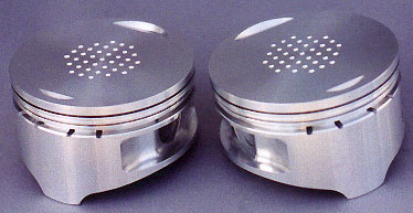
One reason why some people have dimpled pistons, is that unlike a rotary, they are trying to keep fuel insuspension since it really isn't going anywhere. It enters the cylinder and then has to hang around until the piston comes back up. It's not flowing anywhere anymore so it would have more of a tendency to stick. In the rotary, the air is turbulent as it is always moving. This can help or hurt us depending on where it is.
Let's say we had an amount of fuel equal to 10. Again the number means nothing in the real world. Now lets say that this fuel is injected in the intake manifold. By the time it gets to the spark plugs, some of it has spread to far reaches of the combustion chamber where the flame travel doesn't really get to. Let's say we burn 7 out of this 10. That leaves us with 3 left that goes out the tailpipe. That means our a/f ratio at the tailpipe is reading rich. Now lets say that we have direct injection and that it's control allows us to only inject 8 worth of fuel. Let's say we burn 7 of it since more is in a usable location. That leaves us with 1 left over going out the tailpipe. Notice that the exact same amount of fuel was actually burned. The leftover quantity getting read in the exhaust however is very different. In the case of the DI engine, it's far leaner. What matters is at the plug not the tailpipe.
I laugh when people spout out "safe" a/f ratios for various setups. A "safe" ratio is one that doesn't detonate or suffer from preignition. The actual number on a guage is irrelevant. If it shows 14:1 but runs fine and has no breakup issues, it's not a dangerous ratio. There are lots of people leaving power on the table because they don't believe what they see. Keep in mind that at the plugs, the ideal a/f ratio is somewhere around 13:1 or so for max power.
One reason why some people have dimpled pistons, is that unlike a rotary, they are trying to keep fuel insuspension since it really isn't going anywhere. It enters the cylinder and then has to hang around until the piston comes back up. It's not flowing anywhere anymore so it would have more of a tendency to stick. In the rotary, the air is turbulent as it is always moving. This can help or hurt us depending on where it is.
10-15-09 | 11:46 AM
#61
Thread Starter
Joined: Aug 2005
Posts: 255
Likes: 0
From: north california
i do agree that the fuel being used controls the flame front speed IF it's on the exact same engine. But, i don't think the flame front even looks the same in a diesel engine of today, compared to the same diesel engine using mechanical injection versus modern direct injection. We aren't squirting fuel at the rotor face, but pushing a high pressured mist through the entire combustion area, so that flame front may not even reach the outsides, but more, occur there to begin with. This is why i'd like to see what the difference looks like between the two injection styles. This is only my theory. As far as a/f ratios and stuff goes, i'm not too worried about yet, i will consider that "fine tuning" once i get this thing running. And the idea of intake manifold really doesn't apply at all as it will be little more than a way to point the air in the right direction (into the engine). thanks for putting so much time and effort into the posts and responses you've had here.
10-15-09 | 01:43 PM
#62
Hey kiddo, Not until now. Thanks. It was just an Idea. I'm not sure if your comment is sarcastic or insulting?
Valves too...

http://www.williamsmotowerx.net/valves.htm
Sorry just trying to contribute something to the thread. Good Luck, Hulk!
Valves too...
http://www.williamsmotowerx.net/valves.htm
Sorry just trying to contribute something to the thread. Good Luck, Hulk!
10-15-09 | 02:21 PM
#63
Diesel engines are actually quite interesting to study in regards to how the fuel is combusted. Lots of technology has changed to improve all piston engines. In a diesel, the biggest advancements have come in the form of very high pressure direct injection. They've actually been direct injected for quite a while but not at the pressures they are at today.
Diesel fuel is interesting. You never see an octane rating with it. Only a Cetane rating. Diesel fuel, depending on the formulation actually has an octane rating somewhere between 20 and 40. That's it. However it burns so slowly compared to gasoline that low octane really isn't much of an issue. Or is it?
There were many diesel engines that used to have low compression ratios. CAT engines from the 70's come to mind. Back then they used roots style superchargers on their engines and very low compression ratios. Less than 8:1. Why? There are 2 types of compression ratios. Everyone thinks in terms of static compression which in their case was around 8:1. That is merely the difference between the chamber at it's largest vs the chamber at it's smallest. None more complex than that. The other type of compression ratio, and the one that really matters, is the dynamic compression ratio. This is based on volumetric efficiency. If the engine is running at 100% VE, it's dynamic compression is the same as it's static compression. However if it is running at less than 100% VE, as most engines do most of the time, the dynamic compression ratio is less.
Lets say the engine is running at 80% VE. This means that the engine is taking in only 80% of the air that it can physically hold. Sounds weird as you think that there has to be air in there. Think in terms of density. If it's at 80% VE, the air in the engine has to be at a lower than ambient pressure. Ever looked at a vacuum gauge on the intake manifold at part throttle? Heck even at full throttle it may not read ambient until very high rpms. When the engine is at 80% VE, it will rotate through 20% of the compression phase before the air in the chamber even reaches ambient outside pressure. For all intents and purposes, we may as well just say we've lost 20% of our compression ratio. The 8:1 compression engine is effectively behaving like a 6.2:1 compression engine. It's the dynamic compression ratio that matters and this is what forced induction affects. If you bolt on a turbo, your static compression ratio doesn't change at all. If it was 8:1 without the turbo, it's still 8:1. The chamber size and shape doesn't change. However it adds more air which raises the dynamic compression ratio.
Now let's get back to that CAT engine. A diesel engine will generally run at a higher dynamic compression ratio than a gasoline engine since it doesn't have a throttle plate in the way. However in the case of the 8:1 compression CAT engine, even that isn't enough to compression ignite diesel fuel. That's where the roots blower comes in. Since it is positive displacement, it can be set up to provide a certain amount of boost at nearly any rpm. Due to the nature of the design, that boost is always the same regardless of rpm. That's actually not quite true due to sealing losses but you get the idea. The point of the roots blower is to raise the dynamic compression high enough to ignite the diesel through compression ignition. A turbo couldn't have done this on these engines as it wouldn't have spooled up enough to get the thing started.
Now why did they have to run such a low static compression ratio? It had to do with the location of diesel fuel injection. It was basically through a carb on the intake. It was not direct injected. A neat thing happens during compression. When you compress air, it will heat up a certain amount. However when you compress air and fuel, it will heat up even more! There are many people that will argue this saying that can't be true as many turbo cars run very rich to cool the charge and avoid detonation. They do run rich to avoid detonation but not because they cooled the charge down appreciably. I richer mixture is harder to ignite. When it gets extremely rich it get s real hard to ignite and flame front travel is very slow. This is one phenomenon that you would be interested in as density affects flame speed. Many of these overly rich cars will typically have more advanced timing too. They need to. Their flame front speed is slow.
By injecting the very low octane diesel fuel into the intake manifold, the added heat from compression of both it and air together caused preignition. This was no different than any other low octane fuel with high compression. The solution was the only thing it could be. They lowered the static compression. It's the static compression that has a greater effect on preignition tolerance (mostly but not entirely). Charge heating has a big effect as well. It's the dynamic compression that makes power as more air can mix with more fuel.
Later on, mechanical direct injection was employed and instead of the low few psi fuel pressures, a cuople hundred psi could now be used. This allowed less heating of the compressing mxiture and compression ratios went up. Todays engines have many features that have helped efficiency even more. They are staggering intake runner lengths and valve timing. Direct injectors have very focused spray patterns to only spray in the locations that they want rather than getting wasted through surface tension losses on the cylinder walls and pistons which is what the dimpled units try to reduce. Modern injection also uses multiple small pulses strategically timed to aid in more complete combustion at precisely when it has the most effect. As a result they are also quieter, cleaner, and more efficient.
There really is a lot to learn about the dynamics of internal combustion.
10-15-09 | 04:52 PM
#64
Thread Starter
Joined: Aug 2005
Posts: 255
Likes: 0
From: north california
the delphi fuel system will give me the high pressure and i could mount the injector(s) anywhere in the housing. i am pretty positive richer fuel mixtures ignite easier but that may only be gas engines and the flame front is indeed slower. a form of boost was always the plan but a supercharger to get dyn. comp. up may be a must. following suite from the current diesel industry with high comp. and boost is my goal. i want a running n/a engine before i go for the boost if i can. instead of changing just the rotor i really wanna see what i can come up with for changing the housing. making a way to get proper flow through the comb. chamber. with multiple injections from a single injector is gonna be the key for fuel delivery. do you see a small chamber being more effective than having runners in the housing to allow air to flow as freely as possible.
10-15-09 | 05:11 PM
#65
Richer mixtures burn slower but as with everything else there is a "not always" associated with that. Fuel burns within a certain a/f range. Get outside of that range and it's not combustable whether too rich or too lean. Obviously there must be a point on each end where flame speed speeds up, an a/f ratio where flame speed peaks, and then on the other side it must slow down again. The overly rich a/f ratios that many turbo people like to tune for in the name of safety are so close to being unignitable that the flame travel is slow. It is why they can advance timing. A faster flame front speed is a trait of an easier igniting fuel. Diesel fuel burns very slowly (relative to gasoline). You can damn near drop a match in a pool of it and have it just go out.
10-15-09 | 09:45 PM
#66
Thread Starter
Joined: Aug 2005
Posts: 255
Likes: 0
From: north california
so, we are right back to our problem of static cr. i think i want to fill the bath and create a tunnel through the peanut to allow easy movement between the two halves of the chamber. at the leading end and trailing end i think it will funnel outwards and the rotor face will match, creating a pocket or complete tunnel to concentrate the fuel spray. i would also like to locate the injector (just one per rotor to begin). i would like to eliminate as much of the top cc as possible for helping raise compression, so really move the entire timing of the engine much later. again, i can't thank you enough for taking the time and energy to give me information, input, and anything else you feel the need to add to this sweet *** rx7 club?
10-16-09 | 02:46 AM
#67
Full Member
Joined: Mar 2009
Posts: 92
Likes: 0
From: Iowa
In response to the valve pic above: http://www.allpar.com/fix/holler/valve-prepping.html
10-16-09 | 09:35 AM
#68
so, we are right back to our problem of static cr. i think i want to fill the bath and create a tunnel through the peanut to allow easy movement between the two halves of the chamber. at the leading end and trailing end i think it will funnel outwards and the rotor face will match, creating a pocket or complete tunnel to concentrate the fuel spray. i would also like to locate the injector (just one per rotor to begin). i would like to eliminate as much of the top cc as possible for helping raise compression, so really move the entire timing of the engine much later. again, i can't thank you enough for taking the time and energy to give me information, input, and anything else you feel the need to add to this sweet *** rx7 club?
Fuel injector location is also going to get interesting. The farther around the engine you get towards the spark plugs, the higher your fuel pressure needs to be. We can get away with a couple of psi in a carb and less than 40 psi with injectors in the intake manifold. Start upping that pressure as you try to install the injectors farther and farther into the compression stroke. As you move that direction, you also need finer and finer control of the injector times. You aren't going to just be able to use any old ecu after a certain point. That point is roughly straight on top of the engine with the injectors pointing straight down.
When you inject fuel into the intake manifold, with properly timing the fuel spray is beneficial, it's not necessary. Carbs just dump raw fuel into the intake regardless of whether a port is open or not. As you get towards the ignition point, closer and closer control of fuel injection becomes a must. You don't just want to spray fuel in at any rate and hope it does it's thing. You want higher fuel pressures and lower duty cycles. You have less available time to get the fuel where you want it which means you need to get more of it in during that amount of time which is why you need higher pressure. You don't want an apex seal crossing over a spraying fuel injector. You need to have an ecu that allows you to program in at what point in engine rotation you want the fuel injection event to begin. Motec is the only one that comes to mind.
Spray pattern of your fuel injectors and the direction they are pointed will also have a big role in how well it works. Mazda has been playing with direct injection in rotaries for over 30 years now and we still don't have a production version. They've tried many different iterations and each one has it's own set of issues to overcome. Early designs they did called DISC and DISC II were so efficient that they didn't need a throttlebody. They varied the engine rpms through nothing but fuel just like a diesel engine. Of course this was also on a test stand at 3000 rpm. Whether or not it worked through a full rpm range I don't know. The reason we didn't see it was political. States required a cat be fitted to all gasoline powered vehicles. It's a simple rule but one that needed to be taken literally and it had to function. With an engine that has no throttle such as a diesel or the early test DI rotary, due to the surplus of air, the exhaust temperatures run pretty cold compared to standard gasoline engines. This meant that they couldn't heat up a cat to operating temperatures.
The engines could actually pass emissions standards of the day without the cat. However the rules said a cat had to be there and be functional. So much for rules being set for a reason! Mazda ran more tests to find out how they could get the cat up to operating temp and their solution was simple. They added a throttleplate. This decreased the efficiency of the engine and made it dirtier with worse emissions. However the exhaust was hotter and it could be fitted with a cat. It was actually cleaner and more efficient throttleless without a cat than it was with a throttleplate and a cat. See how politics works? They'd rather have it dirty with a cat that cleaner and without one. At this point they pretty much moved back to where they were and any efficiency gains from DI wasn't worth the effort over what they already had.
Today things are a bit different. We have better technology and combine that with a revised rotor geometry it looks like it may actually come true soon. Hopefully. I think the new shape and size is what is keeping the rotar principle alive. I think the 13B as it is, was pretty much maxed out. They played with tons of different options trying to get better and better results. They've played with porting, rotor dish shapes and locations, spark plug locations, number of spark plugs, surface coatings, injector locations, various types of direct injection and many different iterations of it, as well as many other things. The best they got was the Renesis. The breakthroughs of the 16X don't come from anything other than the new rotor geometry. They've tried everything else.
In the end I think you are fighting a huge uphill battle on a front in a war that was started 40 years ago. The problem is the front you are fighting was where the line was decades ago. The front has moved well on from there and progressed into new territory. I think where Mazda is today is something that you'd like to achieve on your own. When I say that I mean in terms of changing rotor shapes and sizes and playing with other technologies to make a superior engine. That's a great goal but in order to accomplish that goal, you need to start with a platform that has that potential. Modifying an existing engine isn't the way to do it. There isn't much more to accomplish with it. You need to start from scratch. Anything you try on a 13B has probably already been tried and there is also probably an equally good reason why we don't see it.
Keep thinking though. That's how you learn. At some point you might think of something extraordinary so brainstorming and talking things out is always a good thing.
10-16-09 | 10:37 AM
#69
Thread Starter
Joined: Aug 2005
Posts: 255
Likes: 0
From: north california
i agree with you in the fact that they have pretty much maxed out the 13b. the 12a, i'm sure is pretty close to it's maximum gasoline potential. what i don't think is true, is that either have put THAT much time into diesel technology. for direct injection the way i'm talking is 100 percent diesel. i'm gonna inject fuel at the point of high combustion chamber pressure basically. my idea basically started with putting a 30,000psi direct injection injector into the stock spark plug location. the fuel control is through a delphi system that can be adapted to any 4, 6, 8, or 12 cylinder engine and has it's own electrically driven or belt/gear driven pump, it's own injectors. As far as ideas go, i am a fitness coach, and at a VERY elite level, but sometimes when i can't get someone to move quite right, there's been a 4 year old int he room that just simply saw the situation through different eyes, and was able to say it in exactly the way it needed to be said for the client to understand. Sometimes it just takes a little bit of a change in viewpoint. Oh, and i'm using a 12a engine to begin with.
10-16-09 | 11:15 AM
#70
They definitely haven't worked a whole lot with diesel in that engine. Others have though and they have all faced the same limitations and that is compression ratio. This is why they've all needed spark ignition. Gasoline DI is pretty relevant to diesel as the line between how each works keeps getting blurrier and blurrier. Gasoline DI is trending towards modern diesel design in many ways. Fuel pressures are getting higher and higher, although WAY lower than diesel due to the properties of the fuels. Compression ratios for modern diesels is actually going down a little while modern gasoline engines are going up. Both are favoring turbochargers and DI is working towards eliminating the throttle plate. GM even has a gasoline compression ignition engine working on the test stand.
Since we need to flow air through the engine, and since there is a flame front that travels outward pushing on the rotor face, it doesn't really matter what fuel we are using. The same phenomemon at are work and the same issues will need to be overcome. Those are just inherent limitations of the engine. If they weren't issues, I guarantee we'd be seeing diesel rotaries out there.
Even if you do get it working, you're going to find an inherent limitation in rpm due to flame speed being so slow. That is typical with all diesels. That will hold peak power down. Without the high compression ratio, you aren't going to get tons of low end power although it should be better solely due to the fact that diesel fuel has more energy potential in it than gasoline does. If you did get the low end of a typical diesel, you'll run into a new issue. Engine strength.
The reason why a diesel engine is built so much heaftier than a gasoline engine for the same horsepower level is actually not due to higher compression ratios. A diesel engine also doesn't run on detonation so you don't get the crazy pressure spikes from that. The only reason why a diesel engine is built so tough is because of torque. Horespower does work. Torque doesn't. Think of torque as nothing more than leverage. Torque is basically trying to twist the engine apart.
Let's say we have an engine that can produce 200 ft lbs of torque. Depending on where that torque is in the powerband could make for a fairly large or a fairly small engine. If that 200 ft lbs is at 3000 rpm, the engine is making 114 hp. If that 200 ft lbs is at 8000 rpm, that engine is making 304 hp. We can see that one engine makes nearly 3 times the amount of power that the other one does. However in terms of block strength, they will see the same load exerted on them as applied in the dimension of twist. There are forces in different directions that are different but this alone on dimension alone explains why blocks are typically heavier for diesels.
We can see that the rotary has no solid block. We are relying on dowel pins and to a small extend tension bolts to keep the engine from twisting apart. When people start breaking housings on highly turbocharged cars, it is as a result of the increase in torque trying to twist the engine apart. This is why people add dowels and strengthen the areas are the pins. People also try to strengthen this area by using aftermarket studs but these really just hold the engine together front to rear but they do have some impact on twist.
First things first just try to get it working. Once you atart breaking things, then worry about strengthing them.
10-16-09 | 03:09 PM
#71

Senior Member
Joined: Jul 2009
Posts: 377
Likes: 2
From: England
Interesting stuff. Is is easy to accurately calculate/measure on a rotary how much adding or removing material affects the compression ratio like it is on a piston engine?
Is there enough meat on turbo rotors to remove a little more? Like taking them down to 8:1 or so?
Is there enough meat on turbo rotors to remove a little more? Like taking them down to 8:1 or so?
10-16-09 | 03:10 PM
#72
On the '87-'88 TII rotors, you could pull them down to about 7.5:1 or so and still have enough material. Over the years, rotors have gotten thinner and thinner in the name of weight savings. Modern Renesis rotors can't be changed at all.
10-17-09 | 11:58 AM
#73
Full Member
Joined: Mar 2009
Posts: 92
Likes: 0
From: Iowa
Here's a look at a non-mazda rotor:http://www.youtube.com/watch?v=Sw3-X6Zn3E0
And here's the 5 year old thread to go with it:https://www.rx7club.com/showthread.p...light=supertec
And here's the 5 year old thread to go with it:https://www.rx7club.com/showthread.p...light=supertec
10-17-09 | 02:11 PM
#74
Originally Posted by quattro4now
10-19-09 | 01:28 AM
#75
No, the symetrical combustion chamber in the rotor (MDR Medium Deep Recess) was not just for cost reasons.
MDR rotors produce a later and higher peak gas velocity before the minor axis of the epitrochoid and a very late peak in velocity after the minor axis.
TDR rotors (Trailing Deep Recess have more uniform gas velocity with a peak near the minor axis reaching max velocity before the leading spark ignition and gradually diminishing in velocity.
LDR rotors (Trailing Deep Recess) are also well documented and actually used in production engines.
But the jist of it is that Mazda did research, build and analyze the possible configurations in its dyno facility that had closed circuit monitoring with all data acquisition digitized stored and analyzed with sensor of every type in every part of the engines. The dyno facility cost $3,500,000 adjusted for inflation.
If you dig you can find much of the Mazda data and make Mazda's money spent work for you.