Megasquirt ms2/extra runs stock FC!


 07-03-07, 01:47 PM
#27
MegaSquirt Mod
Thread Starter
what do you need updated? It'll run staged injection, and the 2nd/3rd gen ignition systems.
The 2.x alpha should even run a renesis (minus the throttle body of course).
The 2.x alpha should even run a renesis (minus the throttle body of course).
07-03-07, 07:18 PM
#29
Top Down and Naked...
Join Date: Feb 2006
Location: Orlando
Posts: 1,129
Likes: 0
Received 0 Likes
on
0 Posts
Ok now I'm lost. Here are some pics of what I have. I’m I going to be able to run a turbo fc with this or do I have to get the MS2 chip and the extra board. I have done lots of reading and always get conflicting info or not detailed enough were I can say this is going to run my turbo vert and not blow it up because of ignition issues. I have not yet found a link where it would tell me how to assemble the msns extra DB and still don’t understand how is my ignition going to be trust worthy enough by grinding down two of its teeth. I'm pretty sure it’s all very simple once you know what you’re doing. I really don’t like giving up on things that I start. I mean if I can take an engine out and rebuild it with help of course and make it run with an n/a ecu. How hard can this be.lol BTW this is my hobby. A lot of ppl my age like to do gardening or paint pictures. I like to play with my rotary. Owned my first one in 1983 and this is my seventh seven. Also my first leap to turbo with standalone. OK let me stop blabbing. HELP PLZ!!!


07-04-07, 09:13 AM
#30
MegaSquirt Mod
Thread Starter
You may have found the thread where I was posting as I was doing my development to make it work.
Ken
07-04-07, 09:16 AM
#31
MegaSquirt Mod
Thread Starter
You should be able to run it just fine with the parts above. You can use MS1 or MS2. Either can run the rotary.
The daughterboard should have come with instructions, and if it didn't, you need to contact whoever you got it from for instructions.
You don't need to cut 2 teeth out of the CAS since you have the daughterboard, all you need to do is wire the daughterboard to the MS properly, and the MS to the engine properly. The FAQ still has instructions on doing this, just no pics. I'll be posting pics as soon as someone gives me some (no time to do them myself).
Ken
07-04-07, 11:46 AM
#32
Top Down and Naked...
Join Date: Feb 2006
Location: Orlando
Posts: 1,129
Likes: 0
Received 0 Likes
on
0 Posts
Thanks Ken. I dont have the instructions they didnt come with it. But I will call the guy I bought it from and see if he still has it. But if someone has them saved and can send them to me that would be great. Thanks again AC
07-05-07, 12:42 PM
#37
****** of disaster
iTrader: (1)
Join Date: Aug 2001
Location: Santa Monica, CA
Posts: 1,115
Likes: 0
Received 0 Likes
on
0 Posts
Hey AC, the daughterboard is from GlensGarage.com.
Here's a link to the instructions, they *should* have been in there. Sorry about that!
http://www.glensgarage.com/extra/
You only need to assemble the "VR Sensor 2" section of the daughterboard, the rest is extra stuff that you don't need to run the car.
If after looking at it it seems too daunting of a task, you can always cut the teeth out of the CAS instead.
07-07-07, 02:50 PM
#38
Top Down and Naked...
Join Date: Feb 2006
Location: Orlando
Posts: 1,129
Likes: 0
Received 0 Likes
on
0 Posts
Cool! so all I have to do is put this blue section together. Also what other sections do I have to assemble. Like for power and to hook it up to the main board. Looks like it would be P1 and P8 right? Would that be all?
 07-21-07, 08:02 PM
#40
MegaSquirt Mod
Thread Starter
It ran fine while I had the ms2 hooked up to it. We went back to the stock ECU so we could run ms2/extra on the TII we're working on.
I'll also be buying another MS to put on my own rx7 (the spring meet car was a friend's) as soon as I have my mechanical issues taken care of (oil leak and vacuum leak).
Ken
I'll also be buying another MS to put on my own rx7 (the spring meet car was a friend's) as soon as I have my mechanical issues taken care of (oil leak and vacuum leak).
Ken
07-22-07, 08:57 AM
#41
Top Down and Naked...
Join Date: Feb 2006
Location: Orlando
Posts: 1,129
Likes: 0
Received 0 Likes
on
0 Posts
 08-02-07, 01:32 PM
#43
Junior Member

Join Date: May 2007
Location: Ireland,Dublin
Posts: 13
Likes: 0
Received 0 Likes
on
0 Posts
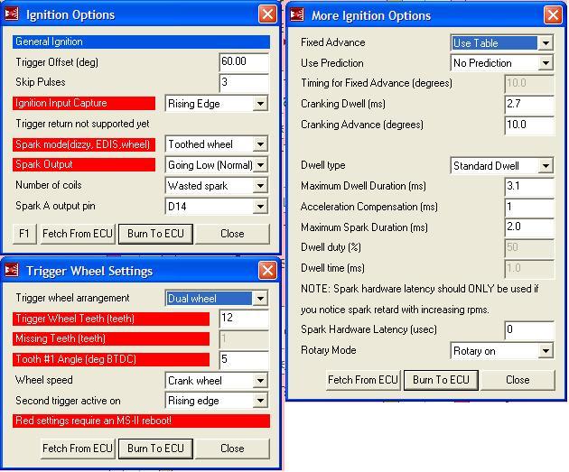
Cas settings ms2
I have built and modded my ms2 with lm1815 circuit included,
and downloaded your latest ms2/extra software.
i have entered as many detail's i could reference from the ms1 setup.
but am unsure of the trigger wheel setting ie dual wheel with or without missing teeth. tooth 1# angle and also
is it wasted spark or coil?
Could you let me know what setting's you used so i can start playing around with this if possible a screen shot.
08-03-07, 01:07 AM
#45
I'm a little confused on some of the installion stuff. What resistors/Capacitors/Diodes, do you NOT need to install on the board (if you could specify their numbers) Also what jumper wires would be needed beside the +5 V on the LEDs. If someone can post a full picture of the front and the back side of the MS that would be great.
Thanks
Thanks
08-03-07, 09:40 AM
#46
MegaSquirt Mod
Thread Starter
I'll have to answer your question when I have time to look up the exact silk-screen designations for each of the parts. (I'm at work right now).
If someone else beats me to it, then I'll just verify whatever that person says when I get a chance to look it up.
As a short answer, you don't need to install the hall/coil - trigger circuit. I'd probably build the rest of the board (except the fast idle circuit) as specified, then mod it as listed in the FAQ. There are pics in the FAQ that I think will cover a lot of what you need too.
Ken
08-06-07, 04:03 PM
#48
Junior Member
Join Date: May 2007
Location: Ireland,Dublin
Posts: 13
Likes: 0
Received 0 Likes
on
0 Posts
Have spent all weekend making a loom installing my fd coils/ignitor and fc cas.
and setting up the ms2/extra.
have all the inputs i need working now.
but cannot get a rpm reading whatsoever
Is there a way of testing just vr1 ne+ & n-.
i have g+ connected to jp4 and i have g- connected directly to ground pin 8.
i also installed the .1 capacitor across gnd and g+ input on the lm1815.
is there a way to test the lm1815 circuit?
08-07-07, 09:57 AM
#49
MegaSquirt Mod
Thread Starter
I don't understand how you've got it connected... G+ and G- should both be going to your lm1815 circuit... G+ to the input of the lm1815, G- to a ground near the lm1815. The output of that circuit should go to jp4.
Ne+ should go through the v3 board's pin 24 using the VR sensor conditioner circuit... Ne- should go to ground.
Ken
Ne+ should go through the v3 board's pin 24 using the VR sensor conditioner circuit... Ne- should go to ground.
Ken
08-07-07, 12:36 PM
#50
Junior Member
Join Date: May 2007
Location: Ireland,Dublin
Posts: 13
Likes: 0
Received 0 Likes
on
0 Posts
Yeah i have ne+(red cas) connected to pin 24.
ne- (white) connected to pin 7.
G+ connected throught pin 25 going to lm1815 input and output going to jp4 on top of the ecu.
G- (white/ black stripe) is connected to pin 8 gnd.
i'm using ms2/extra ver1.0.2
just did a check there and all wiring is connected here are my setting if this helps.
ne- (white) connected to pin 7.
G+ connected throught pin 25 going to lm1815 input and output going to jp4 on top of the ecu.
G- (white/ black stripe) is connected to pin 8 gnd.
i'm using ms2/extra ver1.0.2
just did a check there and all wiring is connected here are my setting if this helps.