Megasquirt JB perf Dual VR board
 12-05-08, 06:06 PM
#1
JB perf Dual VR board
I did some searching and I found a thread where it was mentioned that an additional resistor of value 0.01uF was suppiled with it but, I got an extra capacitor for C4 and it is labeled 0.001 and I installed the other one unknown (to me) value resistor in C4. Don't know if the is the right thing of not or if I need to get another resistor elsewhere. also where do I jumper this thing to the board.
I checked the JBperf site and didnt find and real installation documentation and I read some stuff off the msextra forum but didn't find conclusive answers.
Also do I need to swap and resistors on the MS itself?
I guess I'll let the soldering iron cool down and maybe get back to this tomorrow.
I checked the JBperf site and didnt find and real installation documentation and I read some stuff off the msextra forum but didn't find conclusive answers.
Also do I need to swap and resistors on the MS itself?
I guess I'll let the soldering iron cool down and maybe get back to this tomorrow.
 12-06-08, 09:47 AM
#2
Senior Member
iTrader: (1)

Join Date: Jul 2005
Location: chicago
Posts: 360
Likes: 0
Received 0 Likes
on
0 Posts
I did some searching and I found a thread where it was mentioned that an additional resistor of value 0.01uF was suppiled with it but, I got an extra capacitor for C4 and it is labeled 0.001 and I installed the other one unknown (to me) value resistor in C4. Don't know if the is the right thing of not or if I need to get another resistor elsewhere. also where do I jumper this thing to the board.
I checked the JBperf site and didnt find and real installation documentation and I read some stuff off the msextra forum but didn't find conclusive answers.
Also do I need to swap and resistors on the MS itself?
I guess I'll let the soldering iron cool down and maybe get back to this tomorrow.
I checked the JBperf site and didnt find and real installation documentation and I read some stuff off the msextra forum but didn't find conclusive answers.
Also do I need to swap and resistors on the MS itself?
I guess I'll let the soldering iron cool down and maybe get back to this tomorrow.
You shouldn't have to change anything on the MS itself with the jbperf dual vr board. The .01uF rating is actually for capacitors not resistors. You will want to change c4 on the jbperf dual vr board with a .01uF capacitor. As for whatever resistor is tied to pin 14 (i think its R4), i read somewhere that you shouldn't have to change it to 82k ohms but if ken recommends it why not.
12-06-08, 11:19 AM
#3
I read that the 51k ohm was plenty for that but I may just replace it anyway, Ken usually knows what he is talking about.
As for the capacitor I know I'm supposed to have the 0.01uF. I just didn't know if the unlabeled one of the two for C4 was already 0.01uF. I guess if I was thinking I could just put my meter on it (duh). And as for the uF being for capacitors, that was just a typo on part.
Also connections do I need to make between the vr board and the MS? I have the MS2 V3 and I would like to run the latest msextra.
Right now I already have all the IAC connections connected to JS0 through JS3? IGN is connected to IGBTOUT. IGBTIN is connected to JS10. TSEL is connected to VROUTINV. VRIN is connected to TACHSELECT.
You said I dont have to change anything on the board, what about the addition of the pull up resistors by the LEDs?
*Ok i just measured C4 and im pretty sure I got the right cap in there.
Last edited by ITSWILL; 12-06-08 at 11:32 AM.
Trending Topics
12-06-08, 01:27 PM
#8
Senior Member
iTrader: (1)
Join Date: Jul 2005
Location: chicago
Posts: 360
Likes: 0
Received 0 Likes
on
0 Posts
if you want follow how h4in did it in his instructions and substitute the lm1815 circuit build with the jbperf vr board. so far i have tested my build with jbperf board and an actual mazda cas and it was reading rpm pretty steady.
12-06-08, 02:46 PM
#9
ok so I'll just pick up some 4.7k ohm resistors for the pull ups and do that.
I already have all the iac spots connected to JS0-JS3 for the BAC contol (i believe). Do i have to disconnect those. Also if I disconnect those is there any way to run the BAC?
Also is says to hook the ign spot to the IC ground, fist off I assume I could just hook that to the JBperf boards ground, and secondly I already have IGN connected to IGBTOUT, does that need to be disconnected?
12-06-08, 03:24 PM
#10
Senior Member
iTrader: (1)
Join Date: Jul 2005
Location: chicago
Posts: 360
Likes: 0
Received 0 Likes
on
0 Posts
You will have to disconnect all four inputs for the coils to work. So yes disconnect all the iac spots from js0-js3 and also you have to connect IGN to the jbperf board ground and disconnect from IGBTOUT.
12-06-08, 06:13 PM
#11
OK I can do that. So is there anyway to have BAC?
It seems obvious but do I just take 5 volts from the test area. Do I need ground from the MS ground spot of is that IGN spot sufficient.
The should I jumper pin4 on the IC to the 5V spot on the VR board and pin 6 to the ground. What is IC pin 5 for?
Also where did you mount the board, It looks like I could get it under the MS if i bent the capacitors on the VR board down.
12-06-08, 07:30 PM
#12
Senior Member
iTrader: (1)
Join Date: Jul 2005
Location: chicago
Posts: 360
Likes: 0
Received 0 Likes
on
0 Posts
I will try and take a pic and post it up tomorrow for you. I think once you see how its wired it will make it a little more clear for you and as far as the BAC I'm not sure if you can keep it by routing it to another pin. Ken might be able to let you know about that one. I dont run one so I wasn't worried about it when building it.
12-08-08, 09:28 AM
#16
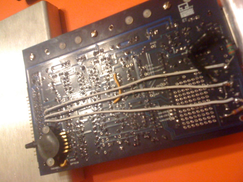
This is what I did. Sorry for the camera phone pics
This showing what I jumpered on the vr board. ( note that I haven't connected anything between the IC 5V and ground, I just left that hole empty)
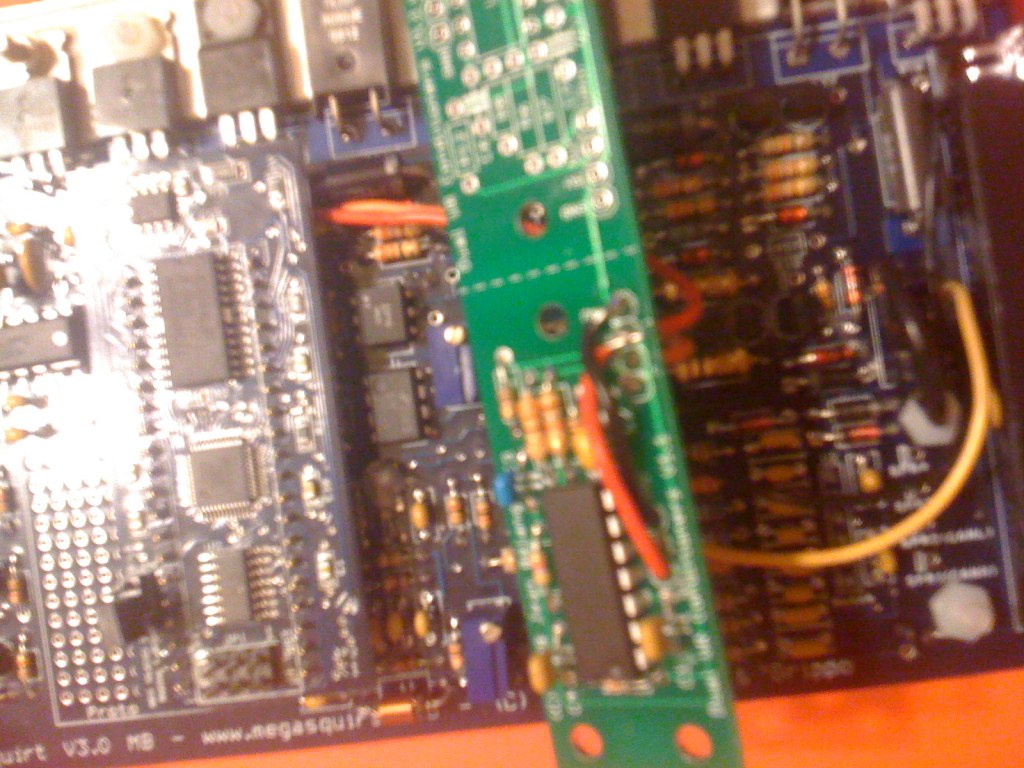
This is showing where I connected to tach and IAC2B
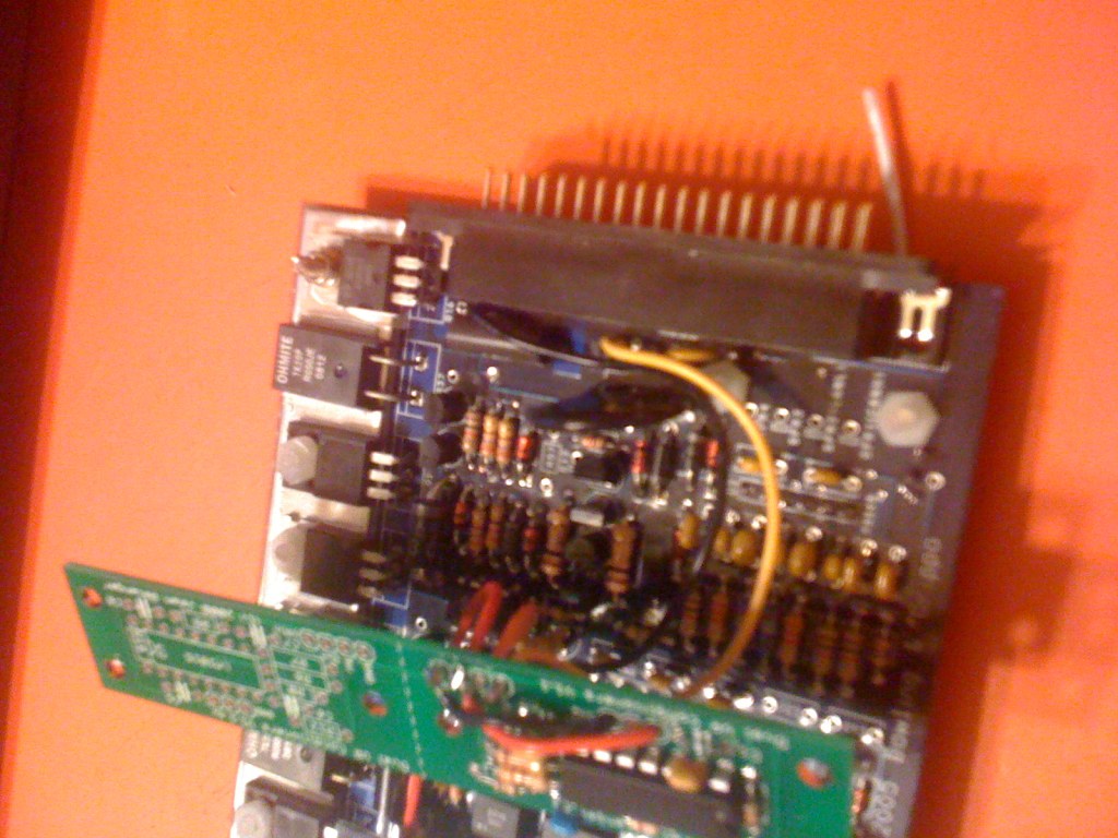
This is showing where I connected to JS10 and +5V
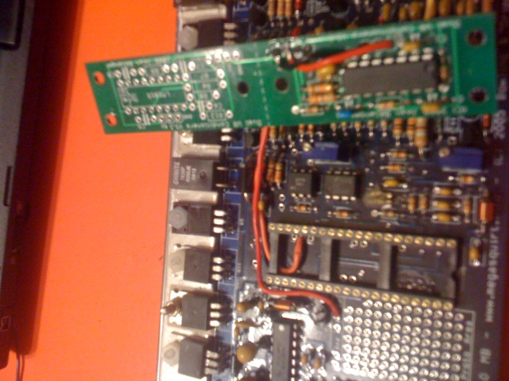
This is showing the connections between the VR board and the MS (it is hard to see the black ign wire but it is on the far right of the others)
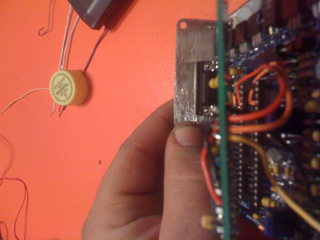
This is showing IAC1A-2A and their connections
This showing what I jumpered on the vr board. ( note that I haven't connected anything between the IC 5V and ground, I just left that hole empty)
This is showing where I connected to tach and IAC2B
This is showing where I connected to JS10 and +5V
This is showing the connections between the VR board and the MS (it is hard to see the black ign wire but it is on the far right of the others)
This is showing IAC1A-2A and their connections
Last edited by ITSWILL; 12-08-08 at 09:42 AM.
12-10-08, 04:14 PM
#18
Senior Member
iTrader: (1)
Join Date: Jul 2005
Location: chicago
Posts: 360
Likes: 0
Received 0 Likes
on
0 Posts
Ok Will I got it down now with jbperf dual vr board so if you need exact connections for this let me know. I just sorted out a few problems I was having with the wiring to the cas.
12-10-08, 04:20 PM
#19
Senior Member
iTrader: (1)
Join Date: Jul 2005
Location: chicago
Posts: 360
Likes: 0
Received 0 Likes
on
0 Posts
As far as pin 5, I think jobro left it open as well and things have been going well. If I'm wrong jobro let me know. I left mine open and so far things are looking good. As for the 5v in to your dual vr board, you should only need one 5v input source as all the 5v ports on the dual vr board are all connected by the traces in the board itself. That's just to clean things up a bit if you want to.
12-10-08, 05:17 PM
#20
ok so i dont need that red wire and that black wire on the jb perf board that I have in the first picture?
Also I talked to Aaron Cake about the BAC and he said it could be run off of the FIDLE as long as you followed the instructions int that blue/purple box when you assembled it.
Also I talked to Aaron Cake about the BAC and he said it could be run off of the FIDLE as long as you followed the instructions int that blue/purple box when you assembled it.
12-10-08, 05:43 PM
#21
Senior Member
iTrader: (1)
Join Date: Jul 2005
Location: chicago
Posts: 360
Likes: 0
Received 0 Likes
on
0 Posts
As long as you have one 5V and one ground wire from the MS3.0 board, every other 5v and ground port on the dual vr board is set.
As far as the FIDLE I read somewhere you could use that instead so you should be able to keep the BAC.
As far as the FIDLE I read somewhere you could use that instead so you should be able to keep the BAC.

Thread
Thread Starter
Forum
Replies
Last Post