actuator wiring
#1
actuator wiring
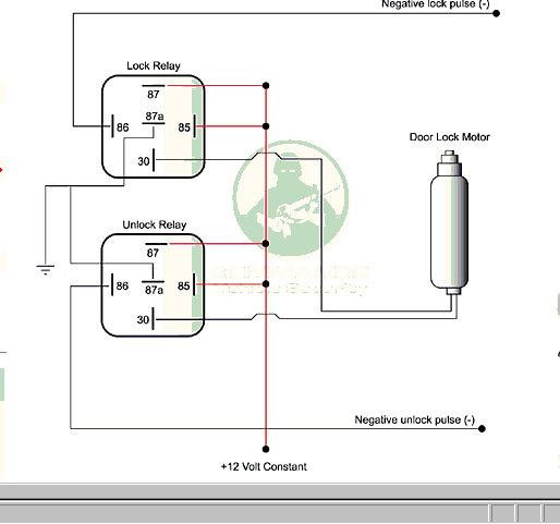
I just finished installing my alarm and everything works. I know the FD needs an actuator to provide leyless entry, only I don't know which wire to hook up to the relay to make the actuator work. can anyone point out which wire needs to be connect in order for this to work
Here is my harness configuration and hookup:
orange - 500mA armed output - DID NOT USE
white - light flash output - connected to red/black wire (fuse panel)
white/blue - remote start act input - DID NOT USE
Black/white - 200mA domelight supervision - DID NOT USE
Green - (-)door trigger - connected to Blue/White (-)
Blue - mulitplexed input zone 4 - DID NOT USE
Violet - (+) Door trigger input zone 3 - DID NOT USE
Black - ground to chasis
Brown - siren output - connected to red wire of siren
Red - constant power - connected to black/green wire
red/white - (-)200mA channel 2 validity - DID NOT USE
Secondary Harness - DID NOT USE
light blue - second unlock ouput
white/black - programmable channel 5 output
violet/black - porgrammable channel 4 output
green/white - factory rearm
gray/black - wait to start input
light green/black - factory disarm
door lock harness: DID NOT USE YET
green - (-)Lock (+) unlock output
blue - (+) Lock (-) unlock output
Remote start primary harness - DID NOT USE
pink/white - 200mA (-) programmable IGN2/ACC2 relay turn on
yellow - IGN input to alarm
pink - (-) 200 mA IGN relay turn on
orange - (-)200mA Acces relay turn on
purple - (-)200mA Starter relay turn on
orange/Black - antiground/ground when armed output
blue - (-) 200mA status output
Heavy gauge inline connector:
purple - (+) output to start (start side) - cut starter cable, connected black/blue wire closest to firewall
green - onboard start kill (key side) - other side of starter cable, connected black/blue wire closest to steering wheel
red - high current 12V input - connected to black/green wire
orange - output to accessory output - connected to blue wire
pink - output to primary IGN - connected to black/white wire
red - high current 12V input - hooked up to the other red wire on this harness
pink/white - output to second IGN - connected to black/yellow wire
red/white - high current 12V - DEI connected back to red wire/harness
remote start secondary harness: DID NOT USE
blue/white - (-)200mA 2nd status/rear defogger
gray - Hood pinswitch input
brown - brack shutdown wire
violet/white - tach input wire
black/white - neutral safety switch
#2
I also have the wiring diagram provided on the forum and the viper 791VX comes with a relay.

The (-) negative lock pulse is what I am looking to hook up to my alarm harness

The (-) negative lock pulse is what I am looking to hook up to my alarm harness
Last edited by silvercvic; 06-22-05 at 11:52 AM.
#3
Thread
Thread Starter
Forum
Replies
Last Post
24seven_dada
3rd Generation Specific (1993-2002)
20
11-10-18 01:03 PM
alexdimen
3rd Generation Specific (1993-2002)
20
10-23-15 02:50 PM


