
Haltech Wiring an RA10 into E6X (FC crank angle sensor)
 02-26-08, 10:45 AM
#1
Wiring an RA10 into E6X (FC crank angle sensor)
First, I haven't had any "trouble" getting consistent readings from the FC CAS without the use of this external reluctor, but I had a few problems at the end of last year which resulted in an engine loss. I've corrected the major short coming (bad fuel pump) but its left a sour taste in my mouth and I'm now going slightly overkill on a few aspects of the entire system.
This is one of them.
So, quite simply, whats the best way to wire this in? What settings on the internal switches work well for an FC trigger? After I wire it in, I change my settings in the Haltech to Hall effect and call it a day?
Any help is appreciated, thanks.
EDIT: I've put in an email to Haltech, but hae no response as of yet.
 02-27-08, 06:00 PM
#3
OK
So I figured out which is + and - coming out of the CAS....
Now, my thought is I will take the home channel, and simply run the + to +IN and the - to -IN...........then connect the haltech wires to +OUT and -OUT just like its currently wired. The ndo the same for the trigger channel......
Seems straight forward, but which wires do I ground? The instructions say "if neither wire in the system is grounded, you must ground one. It doesn't matter which" 2 questions on that:
1) Is our CAS a grounded type?
2) If not, do I ground one wire on each channel? And if so, I am simply tieing a ground into the wire, not deadending it on the chassis, correct?
Also, any information on which switches to turn on for each channel, or any info on setting up the Haltech afterwards is appreciated. Haltech AUS simply sent me a digital copy of the instructions I already have and gave no helpful information, so far anyways.
02-28-08, 07:56 PM
#6
If you look at the wiring diagram for the E6X you will see that the 2 ground wires for the CAS(blue and red) go to pin 26... you will also notice all the other grounds that run to pin 26... everything that runs to pin 26 gets grounded... so to answer your question, yes it's grounded

Trending Topics
02-29-08, 04:41 PM
#9
EFI Tech Wannabe
iTrader: (1)
Join Date: Sep 2003
Location: D.R., USA, the world...
Posts: 2,405
Likes: 0
Received 4 Likes
on
4 Posts
The RA10, or any reluctor adapter for that matter (MSD 8509), just has 1 wire as the signal output and that is fed to either the main trigger input (yellow wire) and/or the home trigger input (green wire) no need for the trigger input grounds to be used.
The reluctor adapter does get the + and - wires to each inputs.
The reluctor adapter does get the + and - wires to each inputs.
02-29-08, 04:51 PM
#10
So there's no need to connect the negative outputs on the RA10 to the corresponding wires on the Haltech sheilded cable? Cuz that was my plan, just basically cutting the wire and running the + CAS wires into the + inputs on the RA10, the - CAS wires to the negative inputs on the RA10 and then simply connect all the shielded cable wires to the ones they came off of....
EDIT: You're saying to do the above, but just hook the sheilded cable up to the + outputs only? So when I'm done I'll only have two wires from the shielded cable hooked into the RA10?
EDIT: You're saying to do the above, but just hook the sheilded cable up to the + outputs only? So when I'm done I'll only have two wires from the shielded cable hooked into the RA10?
03-05-08, 09:44 AM
#12
The instructions that come with the unit will have a pinout for the plug you are supposed to wire, this is helpful (Claudio must've been lol'ing at my last question) I tried to attach the .pdf but its too big.
But basically, if you're looking into the rear of the plug (or looking straight into the RA10) its oriented like this:
8 7 6 5
4 3 2 1
1= Main + (CAS red wire)
2= Home + (CAS green wire)
3= GND
4= Home channel out (Haltech green wire)
5= Main - (CAS white wire)
6= Home - (CAS white/black wire)
7= 12v
8= Main channel out (Haltech yellow wire)
Then, in your trigger setup menu, change both main and home channels to Hall effect mode and crank it over to see if you get signal.
I am currently using dipswitch 4 in the RA10 on both channels, but am a little bit away from cranking it over. So in a week or so, I'll post back if another set of switches works better.
Also, I mounted mine on the passenger side strut tower/wheel well with rubber mounts to isolate it from vibration. THe unit has a healthy heat sink ontop, so I don't think this enviroment should bother it too much.
(Claudio must've been lol'ing at my last question) I tried to attach the .pdf but its too big.But basically, if you're looking into the rear of the plug (or looking straight into the RA10) its oriented like this:
8 7 6 5
4 3 2 1
1= Main + (CAS red wire)
2= Home + (CAS green wire)
3= GND
4= Home channel out (Haltech green wire)
5= Main - (CAS white wire)
6= Home - (CAS white/black wire)
7= 12v
8= Main channel out (Haltech yellow wire)
Then, in your trigger setup menu, change both main and home channels to Hall effect mode and crank it over to see if you get signal.
I am currently using dipswitch 4 in the RA10 on both channels, but am a little bit away from cranking it over. So in a week or so, I'll post back if another set of switches works better.
Also, I mounted mine on the passenger side strut tower/wheel well with rubber mounts to isolate it from vibration. THe unit has a healthy heat sink ontop, so I don't think this enviroment should bother it too much.
03-06-08, 10:40 AM
#13
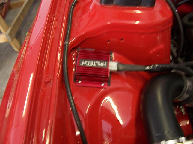
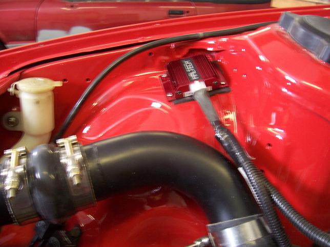
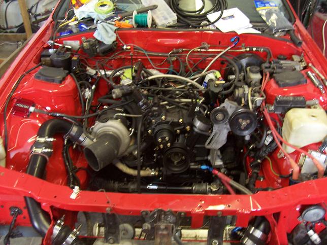
Mounting pics
Here's where i mounted mine.
Had to trim the screws on the inside of the wheel well so they don't touch the tire. I suppose that the best way would be to mount it IN the cabin, but there's not a crapload of room where my ECU is due to looping some unused parts of the haltech harness.
I mounted it with some isolating foam rubber to keep vibrations minimal.
Also, anyone who's had one of these units before, was your board "loose" in the box? I can grab the plug on the RA10 itself and move it in and out. If its broke, Haltech will be 2 for 2 shipping broken pieces to me.
Anyways, here we go: (and I just realized while uploading these that they're blurry as **** lol)
03-18-08, 01:07 PM
#14
Alright:
ECU settings. All I did was switch both Home and Trigger channels to "Hall Effect" mode and rest the ECU. I left the firing edges the same as before which (IIRC) was rising on home, falling on trigger.
Also, a new setting for "Trigger Input Pull Up" becomes available when you switch to HE mode. I simply left it set to "ON" as I wasn't sure which to use.
I noticed immedeatley when cranking the engine over, that I had better "resolution" then before. Using just the FC CAS and E6X I would see RPM of 50 then 188 while cranking until it fired up. Now when I crank I can see 3-35-58-90-134-188-189-188-190 then it'll fire up. Really quite a difference in that regard.
I managed to zero the timing properly with the current settings, and no one at Haltech could answer me as to which setting (on or off) is "correct" for Hall effect mode on this application, so I'm leaving it as is.
Thats about all
12-27-09, 11:38 PM
#15
Junior Member

Join Date: Jun 2004
Location: australia
Posts: 6
Likes: 0
Received 0 Likes
on
0 Posts
The instructions that come with the unit will have a pinout for the plug you are supposed to wire, this is helpful (Claudio must've been lol'ing at my last question) I tried to attach the .pdf but its too big.
But basically, if you're looking into the rear of the plug (or looking straight into the RA10) its oriented like this:
8 7 6 5
4 3 2 1
1= Main + (CAS red wire)
2= Home + (CAS green wire)
3= GND
4= Home channel out (Haltech green wire)
5= Main - (CAS white wire)
6= Home - (CAS white/black wire)
7= 12v
8= Main channel out (Haltech yellow wire)
Then, in your trigger setup menu, change both main and home channels to Hall effect mode and crank it over to see if you get signal.
I am currently using dipswitch 4 in the RA10 on both channels, but am a little bit away from cranking it over. So in a week or so, I'll post back if another set of switches works better.
Also, I mounted mine on the passenger side strut tower/wheel well with rubber mounts to isolate it from vibration. THe unit has a healthy heat sink ontop, so I don't think this enviroment should bother it too much.
(Claudio must've been lol'ing at my last question) I tried to attach the .pdf but its too big.But basically, if you're looking into the rear of the plug (or looking straight into the RA10) its oriented like this:
8 7 6 5
4 3 2 1
1= Main + (CAS red wire)
2= Home + (CAS green wire)
3= GND
4= Home channel out (Haltech green wire)
5= Main - (CAS white wire)
6= Home - (CAS white/black wire)
7= 12v
8= Main channel out (Haltech yellow wire)
Then, in your trigger setup menu, change both main and home channels to Hall effect mode and crank it over to see if you get signal.
I am currently using dipswitch 4 in the RA10 on both channels, but am a little bit away from cranking it over. So in a week or so, I'll post back if another set of switches works better.
Also, I mounted mine on the passenger side strut tower/wheel well with rubber mounts to isolate it from vibration. THe unit has a healthy heat sink ontop, so I don't think this enviroment should bother it too much.
does that matter ? any more info would be appreciated
01-09-10, 10:34 AM
#18
What you guys should know though is that all the ECUs have an onboard adapter. The E6X used the RA8, the E8/11 used the same RA10 as the external box, and the new Platinum boxes use an RA12. You're not getting some magical device that is something you don't already have in your ECU.
Personally, I have had a ton of trigger issues with E6X just like everyone else. They are just down right finicky and I dread the thought of working with them. The E8/11 are much better and you should be able to complete an install without using some kind of external adapter. I've never used one with the E8/11. The Platinums are even better and IMO easier to setup.
All that said, proper installation is imperative. There is a LOT of bad information on this and other sites about grounding the shielding cable for example. The biggest favor any of you can do for yourself is pay very close attention to the routing of the trigger wires. That is usually the source of most problems.
Even with the external adapter boxes the reluctor still needs to generate a signal, and that sine wave signal still needs to have a clean path from the sensor to the box. So there is still potential for noise to enter the signal unless you mount the box directly on the sensor. The external adapter isn't a magic bullet and won't necessarily solve an issue.

Thread
Thread Starter
Forum
Replies
Last Post
trickster
2nd Generation Specific (1986-1992)
25
07-01-23 04:40 PM
befarrer
Microtech
3
08-22-15 05:52 PM