
Haltech New User Haltech Setup Questions
 01-03-10 | 05:08 PM
#1

Thread Starter
Joined: Mar 2007
Posts: 1,029
Likes: 0
From: Appleton, WI
New User Haltech Setup Questions
Hello,
I'm in the process of building my Haltech-powered project car (link in sig), and I've got some questions, as I've never done anything of this magnitude before. I'll keep this thread updated with questions I come across as I work through this
First of all, Oxygen sensors
I've got an AEM wideband sensor and controller already installed on the car. The Haltech also came with a sensor (which I'm assuming is a heated narrowband sensor?)
Can the AEM supply signal for the Haltech? I believe it has a 0-5v output. Should I just install the AEM sensor in my downpipe, just the Haltech, or both?
01-04-10 | 02:58 PM
#3
Thread Starter
Joined: Mar 2007
Posts: 1,029
Likes: 0
From: Appleton, WI
If o2 correction is what I think it is, I'd love to use it. Anything to make tuning easier. I'll dive more into using just the AEM later, just needed to know how many bungs to install.
Thanks! Of course, I will keep this thread updated as questions arise...
Thanks! Of course, I will keep this thread updated as questions arise...
01-07-10 | 01:38 PM
#4
Your wideband sensor should have narrowband output as well. You can use this instead of Haltech O2 sensor.
01-07-10 | 04:59 PM
#5
There is no need for the narrow band sensor or output if you input the wbo2 signal into the Haltech. Also the o2 feedback is for idle and cruise.... Not for WOT. You should not use it untill you have a map that's close to correct anyway or else you'll have a heck of a time setting it up correctly.
01-08-10 | 12:42 AM
#6

Junior Member
Joined: Sep 2003
Posts: 33
Likes: 0
From: davenport ia
The way i did it was used the narrow band to get the car running and then set up the wide band for the final set up. You can do this any way you want but you want to make sure before you get on it the wide band is the one the haltech is using.
02-14-10 | 05:20 PM
#7
Thread Starter
Joined: Mar 2007
Posts: 1,029
Likes: 0
From: Appleton, WI
Just to clarify:
I'm going to cut off the oxygen sensor pigtail on the haltech harness, and then run an additional wire from the output on the AEM gauge to a spare input on the haltech?
I'm going to cut off the oxygen sensor pigtail on the haltech harness, and then run an additional wire from the output on the AEM gauge to a spare input on the haltech?
Trending Topics
02-14-10 | 05:25 PM
#8
02-14-10 | 08:55 PM
#9
Thread Starter
Joined: Mar 2007
Posts: 1,029
Likes: 0
From: Appleton, WI
Because I wouldn't be using it?
Where does the 0-5v signal from the wideband connect to the haltech? is it the orange? wire that is supposed to run to the haltech oxygen sensor?
Where does the 0-5v signal from the wideband connect to the haltech? is it the orange? wire that is supposed to run to the haltech oxygen sensor?
02-14-10 | 10:19 PM
#10
Ok, I will just assume you have e6x haltech. When comes to colors of the wiring it will be different between each version. Anyways 0-5 volts is wideband signal and it can connect to any of you analog inputs and by looking at the wiring diagram of the e6x you got only one - green wire that it says aux in. As far as narrowband I said before your wideband probably has narrowband output as well.... this one you can connect to pin 2 shielded wire (only if you want , not necessery). You wont need 12v supply for the sensor but you might need to ground pin 26. I hope this helps. If you have some other haltech version it might be diff... so let me know. Good luck. btw dont forget to configure your aux input for wideband o2.
02-15-10 | 02:28 AM
#12
Thread Starter
Joined: Mar 2007
Posts: 1,029
Likes: 0
From: Appleton, WI
LS1 coils
I followed the wiring diagram for these, ended up using 2 out of the 4 wires in the injector loom. The remaining ones are IGN and GND. I was going to pull the IGN from the original IGN fuse. Good idea?
CAS
I've heard this is a major source of headaches and nearly impossible to get a good signal out of. I have the shielding grounded on the ECU side, and I will seperate it from the rest of the loom in the engine bay, but it runs into the engine bay with the rest of the wiring. Should I take it completely out of the loom, leave it as-is and see how it works, or give up and rig up a trigger wheel?
02-15-10 | 09:17 AM
#13
Aux In is not for use with a sensor. Either use the Spare A/D or the O2 input. The AEM should output the correct 0v = 10:1, 5v = 20:1 scale for the E6X to display the correct AFR. If you can't get them to jive I'd log the raw voltage output of the AEM and do the conversion in your head or on a spreadsheet.
You'll be able to get a fine trigger signal for the CAS if you take your time and pay attention to details. There is no additional grounding of the trigger loom that's needed. It is grounded through the Haltech harness and that's all you need. Carefully route the harness to avoid any electrical noise (alternator wiring, ignition coils, ignition wires, etc.).
Not sure where you're pulling connections for the LS1 coils from the injection side of things. You shouldn't. Pins A and B on the LS1 coils connect to ground. I like to connect these to the rotor housings. Pin C is your trigger input from the ECU. With the E6X you will need to configure the ignition as wastespark, so L1 and L2 will connect to IGN 1 from the Haltech. T1 will connect to IGN 2 and T2 will connect to IGN 3. Pin D needs 12v switched.
Since the E6X doesn't have a separate circuit for the ignition side of things in the fuse block I would pull power for the coils directly from the battery, through a fuse and a relay. You can use the injector output to switch the relay. Another option, that would be cleaner, would be to source the pins for the fuse block and use the unused space there as your fused source for the ignition. Use the unused 87 pin on the main power relay to feed this fuse. The fuse block and pins that Haltech uses is usually available at places like Autozone.
02-15-10 | 11:14 AM
#14
Thread Starter
Joined: Mar 2007
Posts: 1,029
Likes: 0
From: Appleton, WI
Thanks for the help and being patient!
I already have the CAS terminated, I think I will undo it and take it out of the harness. The grounding I was speaking of was the extra black wire coming out of the loom, it looked to be connected to the shielding in the pinout. I've got an extra 8 guage wire laying around, I'm going to run that from the battery to the frame near the CPU and ground everything I have on it.
Disregard most of this image, I stole it.

Regarding the power for the coils...I understand what you're suggesting, with the relay and extra wiring...I'm wondering if I can connect the coils to the far right fuse in the left picture. This should be an unused, switched, fused source right next to where the coils are going to be, rather than running more wire from the back of the car to the front.
I already have the CAS terminated, I think I will undo it and take it out of the harness. The grounding I was speaking of was the extra black wire coming out of the loom, it looked to be connected to the shielding in the pinout. I've got an extra 8 guage wire laying around, I'm going to run that from the battery to the frame near the CPU and ground everything I have on it.
Disregard most of this image, I stole it.
Regarding the power for the coils...I understand what you're suggesting, with the relay and extra wiring...I'm wondering if I can connect the coils to the far right fuse in the left picture. This should be an unused, switched, fused source right next to where the coils are going to be, rather than running more wire from the back of the car to the front.
02-16-10 | 11:36 AM
#15
The EGI fuse is not switched. You can pull power from it but you will need to run it through a relay that is switched.
No need to run ground wires all over the place. When you do that you introduce ground loops that can create offsets and/or more electrical noise. You should have the battery ground running directly to the engine block and one or two cables of around 8 gauge running to the frame. Nothing else needed from there. That's how the stock system is setup and what one should shoot for when building an aftermarket system.
No need to run ground wires all over the place. When you do that you introduce ground loops that can create offsets and/or more electrical noise. You should have the battery ground running directly to the engine block and one or two cables of around 8 gauge running to the frame. Nothing else needed from there. That's how the stock system is setup and what one should shoot for when building an aftermarket system.
05-17-10 | 03:58 PM
#17
Thread Starter
Joined: Mar 2007
Posts: 1,029
Likes: 0
From: Appleton, WI
Okay! I'm really getting close now, have a base map loaded on the Haltech, and I think I'm ready to see if it turns over.
I turned the key to START and nothing happens. I'm pretty sure this has something to do with the physical wiring to the starter rather than something with the haltech, but I was wondering what kind of stuff I should start looking at to chase this down?
I have the wideband oxygen sensor hooked into the spare A/D....how do I set this up in the software?
05-17-10 | 08:30 PM
#19
Thread Starter
Joined: Mar 2007
Posts: 1,029
Likes: 0
From: Appleton, WI
OH MAN! I am excite.
Swapped starter solenoids after some testing and she turned right over! I forgot to disable the fuel injectors and immediately smelled fuel in the exhaust.
Are my LS1 coils supposed to spark when the key is turned to RUN?
I went in, disabled the injectors, and turned the key to run again. BOOM! I got one detonation out the turbo that was loud as hell. I've verified this with a timing light..it flashes once when the key is flipped to run, and then more as it's cranked.
05-17-10 | 08:40 PM
#20
Ignition Autosport
Joined: Apr 2010
Posts: 109
Likes: 0
From: New Zealand
Yes, they will charge/discharge when you turn the key on. The ECU trigger is what does it, doesn't matter what coils you use. When it is tuned and you don't have excess unburnt fuel sitting in your engine it won't happen.
05-17-10 | 09:59 PM
#21
Thread Starter
Joined: Mar 2007
Posts: 1,029
Likes: 0
From: Appleton, WI
Okay! Thanks!
I'm using Claudio's new user haltech guide (found here) https://www.rx7club.com/forum/showthread.php?t=734988 and also referencing the hitman.
How often does the Engine Data page refresh?
I think I've got the gain set properly to get a steady RPM reading, but it might just be stuck? It seems to refresh about once a second?
Anyone got some hints on setting the trigger angle? I'm trying to zero the timing, I started at 65 angle 11 offset, with the CAS maxed out at one end so the marks line up. The timing light shows that the timing mark is at about 3 o clock on the crank pulley, and some adjustments make it better, some make it worse, but I really can't figure out how to line it up. (example, 55 angle is closer, 50 angle is about the same, 45 is way off) How much should I be adjusting this, and in which direction?
05-18-10 | 10:55 PM
#23
talking head
Joined: Apr 2008
Posts: 2,775
Likes: 14
From: Perth, WA, OZ
did you end up with a 10/65 tooth count ?
also just to confirm with mr Ludwig this statement
while i dont have the lit for an E6x,, i do have the e8/11 stuff and i they have wastespark mode settings as
IG1 =L1 and L2
IG2= aux out /pwm/digital
IG3= T1
IG4= T2
while i know the e6 is non sequential ignititon ( wastespark ),, do they indeed run revised output wiring and thus different to e8/11 ?
also just to confirm with mr Ludwig this statement
"With the E6X you will need to configure the ignition as wastespark, so L1 and L2 will connect to IGN 1 from the Haltech. T1 will connect to IGN 2 and T2 will connect to IGN 3."
IG1 =L1 and L2
IG2= aux out /pwm/digital
IG3= T1
IG4= T2
while i know the e6 is non sequential ignititon ( wastespark ),, do they indeed run revised output wiring and thus different to e8/11 ?
05-21-10 | 02:48 PM
#24
Thread Starter
Joined: Mar 2007
Posts: 1,029
Likes: 0
From: Appleton, WI
Okay, this might be part of my no start issue. 10/65 tooth count? Do you mean tooth offset/trigger angle?
Currently, I have it set to direct fire, with both leading coils run off of IGN1, and T1 and T2 ran off of IGN 2 and IGN3, which are digout1 and digout2.
As far as I can tell, the timing is very close to correct, verified L1 and T1 are close to the timing mark. I think I had it at 90 angle, 11 offset.
I have fuel...computer says injectors are firing, and I can get probably 2/6 or 3/6 faces to fire. Fuel pressure is a gauge verified 40psi while cranking.
I have 110 psi on at least four faces. The other two probably have super glue on the seals yet and will hopefully come out once I get some heat in the engine.
This is a base map that Brian sent me...should be enough to get the car started...
So, why isn't it starting? Alternating unflooding and cranking procedures, and it really, really wants to start, but not quite. Any guesses? Direct fire with the wiring I mentioned above is correct for e6x?
05-21-10 | 06:42 PM
#25
Thread Starter
Joined: Mar 2007
Posts: 1,029
Likes: 0
From: Appleton, WI
After doing a lot of reading, I really think I have everything correct and my problem is very basic...my first guess is that I have a dirty signal from the CAS or the timing is just plain wrong. My second guess is that I screwed up building the engine and insufficient compression isn't allowing it to start.
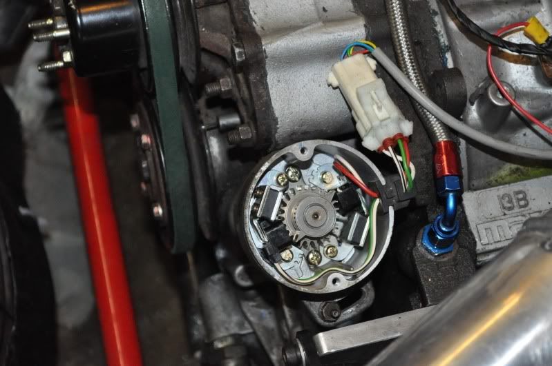
I've inserted the CAS at what I believe to be the factory install...but at 65/11, the timing mark is at about 10:00 on the crank pulley when verified with the timing light. This lines up much better around 100/11, but this doesn't seem close to anything I should be seeing.
Is my CAS off a tooth?
I've inserted the CAS at what I believe to be the factory install...but at 65/11, the timing mark is at about 10:00 on the crank pulley when verified with the timing light. This lines up much better around 100/11, but this doesn't seem close to anything I should be seeing.
Is my CAS off a tooth?