Haltech Haltech Installation Diagrams and Setup Tips
#126
Bougth the haltech from rx7store about a year ago
#127
hey guys, I need help with my Haltech Sprint RE wiring, I have 2 questions.
which wires do I need to hook up a wideband? a AEM failsafe wideband (30-4900) to be exact
also the diagram indicates I wire up terminals 10 and 11 to a switched 12+, does the module not get constant 12v?
thanks in advance
which wires do I need to hook up a wideband? a AEM failsafe wideband (30-4900) to be exact
also the diagram indicates I wire up terminals 10 and 11 to a switched 12+, does the module not get constant 12v?
thanks in advance
#128
AEM failsafe to Haltech Sprint RE wiring/setup
I guess I should give more information on what I need help with lol
I want to be sure on wiring up a AEM failsafe wideband unit to my Haltech Sprint RE and configure it in the haltech program. the wideband controller has a few wires Im not too sure where to hook up. I know the white (aem afr analog output +) goes to the grey/orange (Sprint RE AVI1)
but the wideband also has:
(blue) failsafe lowside ground output for an external auxiliary device (1.5a max), is that even for the haltech?
(yellow) 0-5v+. analog output for MAP. will this work instead of me using the internal map sensor inside the Sprint RE?
(brown) Analog ground for AFR and MAP, connects to sensor ground of ems. im guessing thats for sensor ground (b/w, terminal 22) on the haltech.
(green) rpm input, requires a square wave trigger. will the DPO1/tach ouput work? (v/b, terminal 6) on the haltech
also does the DPO1 connect straight to my RPM gauge cluster?
Once this is hooked up, how will I go about configuring it in the Haltech? please halp

#129
Thread Starter
EFI Tech Wannabe
iTrader: (1)
Joined: Sep 2003
Posts: 2,405
Likes: 4
From: D.R., USA, the world...
Gents, it was recently brought to my attention that some of the FD diagrams had incorrect info on the crank sensor wires. It has now been corrected. Feel free to download them again. So, the + wire on the crank sensors will be the pin to the right on each.
Settings should be for Sport ECUs.
Trigger angle 65
Tooth offset 10
Falling Edges
Reluctor sensors
Trigger/Home -ve to ON.
Sorry for any confusion this might have caused anyone.
Settings should be for Sport ECUs.
Trigger angle 65
Tooth offset 10
Falling Edges
Reluctor sensors
Trigger/Home -ve to ON.
Sorry for any confusion this might have caused anyone.
#130
Hey Chris
Sorry to resurrect this thread from the dead but can you by chance tell me where you found the S6 patch loom schematic? I have looked everywhere for that thing online, I think it's the HT-041322 I'm looking for.
Thanks!
PSI. Im about to finally buy a whole bunch of haltech stuff from you in January!
Skeese
#131
Hey Chris
Sorry to resurrect this thread from the dead but can you by chance tell me where you found the S6 patch loom schematic? I have looked everywhere for that thing online, I think it's the HT-041322 I'm looking for.
Thanks!
PSI. Im about to finally buy a whole bunch of haltech stuff from you in January!
Skeese
#132
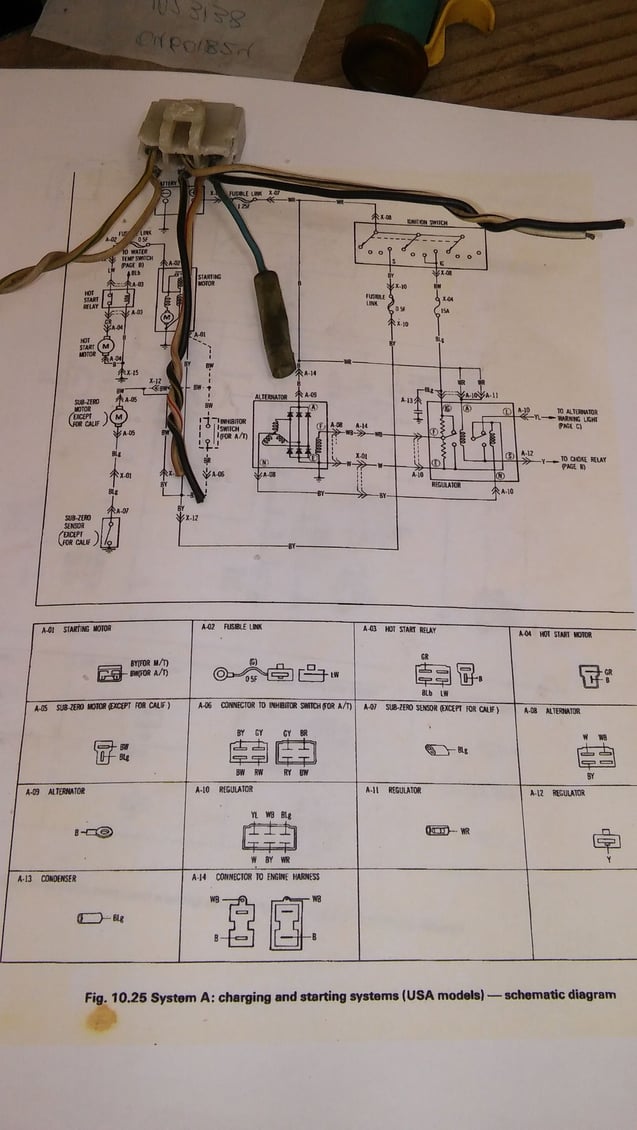
Jumpers at regulator connector SA

Maybe i can resolve two questions at once here I have a 79sa chassis receiving 87t2 implant in process of installing e6k and cleaning up engine bay harness the alt is 70 a s4 I repinned the s4 connector with two of 3 wires on sa harness white/blk top and white bottom
1. I gather the pins at the now removed regulator need jumped out and there are references in many threads but nothing definitive i am attaching a pic of the diagram and clip
2. Haltech switched 12v the grey wire can that be integrated here as well?
that appears to be a fused 12v switched supply
Last edited by Phx79RX; 01-03-17 at 08:49 AM. Reason: Pic
Thread
Thread Starter
Forum
Replies
Last Post
Claudio RX-7
Haltech Forum
5
04-23-19 03:50 PM
82streetracer
1st Generation Specific (1979-1985)
7
08-23-15 10:28 AM


