
Vulcan Autoworx Sleepy Eye Kit
 04-25-13, 04:22 PM
#1
Vulcan Autoworx Sleepy Eye Kit
FIRST AND FOREMOST: THIS IS NOT A GB THREAD!!!!
i will post up a GB once I have everything in order, and have purchased a vendor membership. Please do not ask about price! This will be much briefer than David's original thread, showing just what I have personally done.
Now that that is out of the way, on with the thread.
Thank you to David Hayes for his generosity, letting me duplicate this for our community.
This is a blurry pic of the rod end used in the arm that connects the motor to bucket.
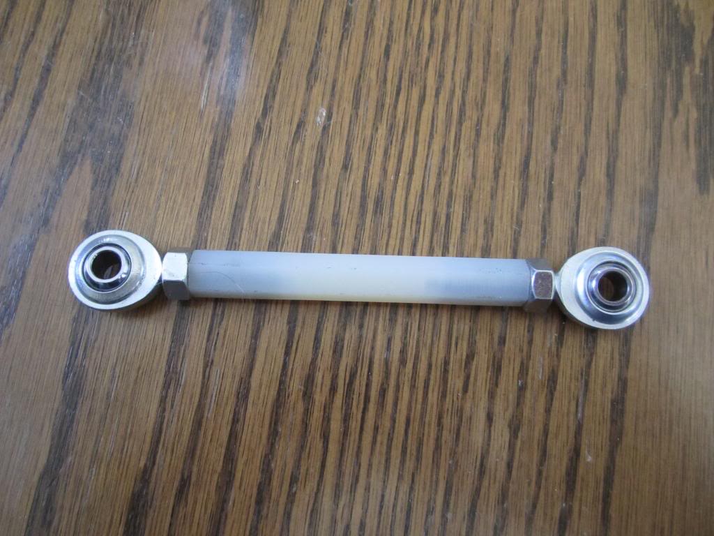
the actual arm
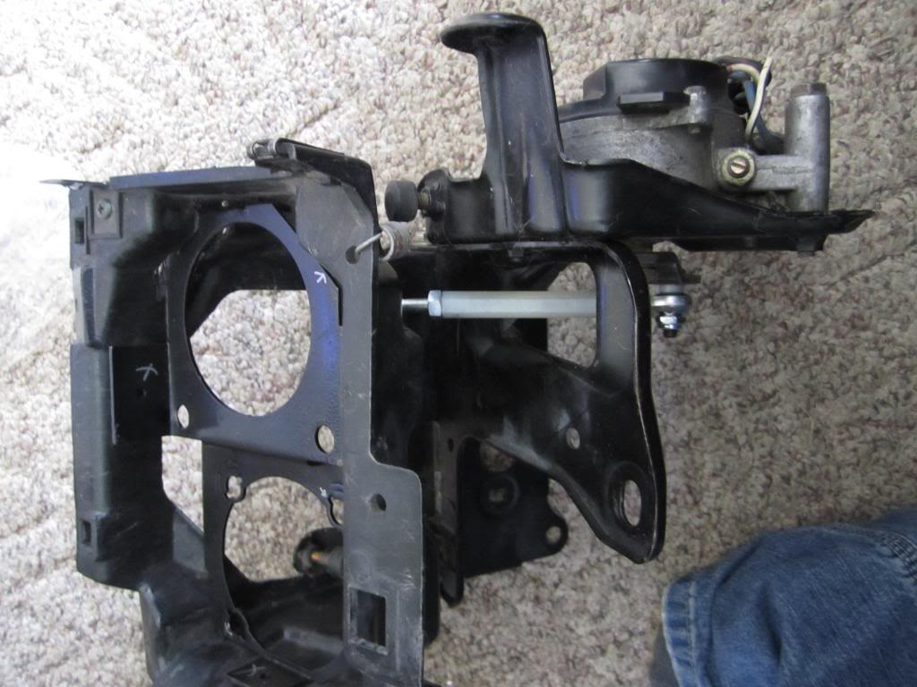
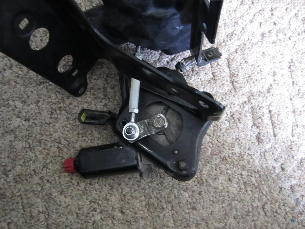
arm installed
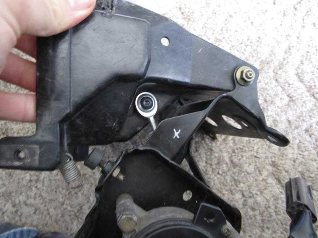
The arm is reasonably easy to install. First you remove the ball on the bucket, this is a simple as removing a nut from a bolt.
Second remove the ball from the mini arm that is attached to the motor. for this remove the mini arm from the motor, just unscrew the nut from the motor. then take the mini arm, and (using an angle grinder or similar) grind the back end of the ball (bolt). just a few seconds is all it takes, then punch out the ball from the rear.
Third, drill out the hole that the ball came out of to a 1/4 inch (this is only slightly larger than the stock hole).
For the reassembly the new arm is used.
First put the 1/4 bolt through the mini arm (so that the threads are on the ball side of the mini arm).
Then put the 1/8 inch Delrin spacer on, followed with the arm. finally threading on the nylon lock nut.
Next reattach the mini arm to the motor with the stock hardware.
To attach the arm to the bucket it is very similar. run a 1/4 inch bolt though the arm, then slide on another 1/8 inch Delrin spacer. Through the bucket, finally using a nylon lock nut to secure everything in place.
There isnt a specific torque requirement here, just make sure it is snug. the purpose of the spacers is to prevent binding of the arm when the motor moves.
To install both arms takes roughly 15 minutes if you go slow.
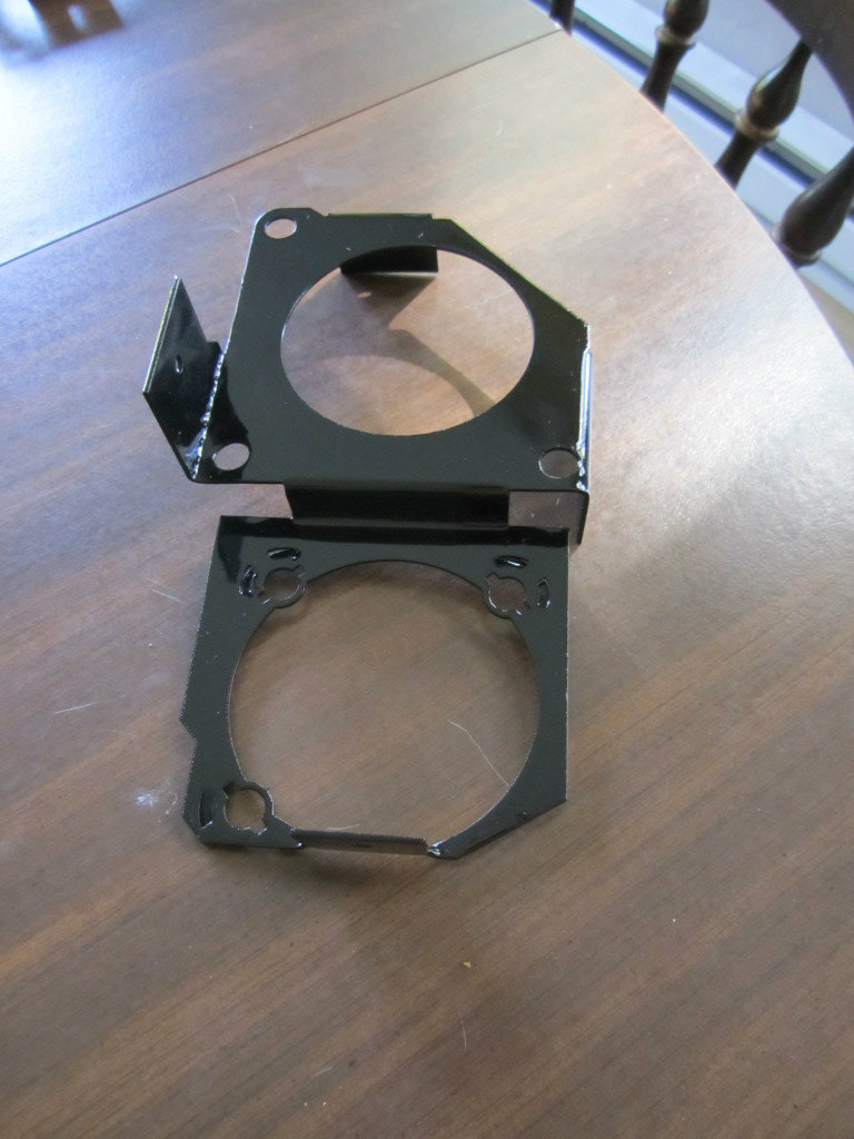
the following are the brackets that allow you to mount the light modules to the stock bucket. (these are an earlier version, though the final version is only minimally altered from this design.
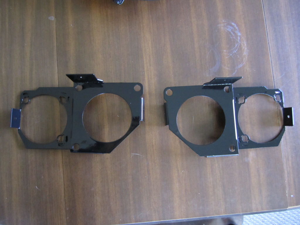
just a different angle.
The installation into the bucket is relatively straight forward. First make one cut...
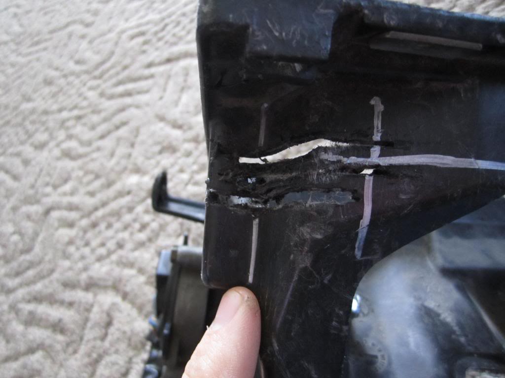
using the edge (that I'm pointing at here), place a straight edge along it. Then continue the line.
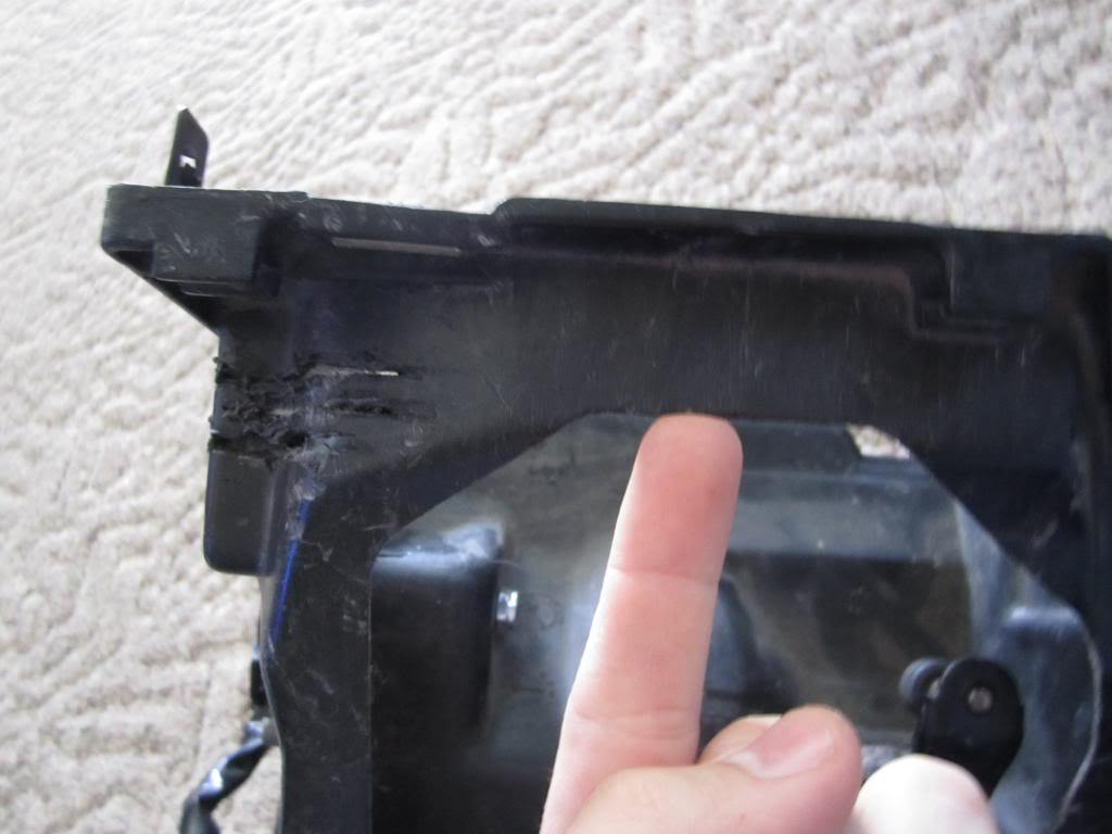

then using the edge perpendicular to the first edge. marking it the same was as the first.
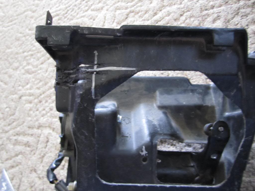
Cut a line along the first line, from the intersection of these lines to the low point indicated below. the cut can be made with a number of tools, a rotary tool is likely the best option (please ignore the excess cuts).
slide the bracket into the slot and push the bracket into the bucket (it will be snug). once the bracket is in secure the tabs to the bucket using screws.
then install the modules and aim them.
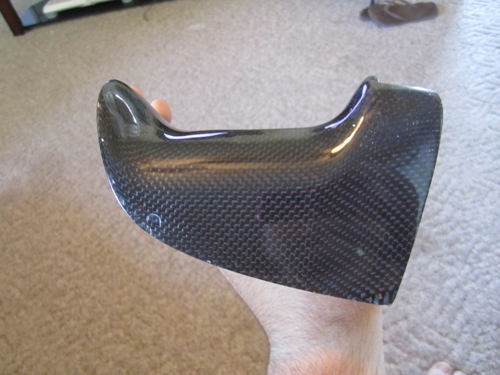
next the shroud install.
i will post up a GB once I have everything in order, and have purchased a vendor membership. Please do not ask about price! This will be much briefer than David's original thread, showing just what I have personally done.
Now that that is out of the way, on with the thread.
Thank you to David Hayes for his generosity, letting me duplicate this for our community.
This is a blurry pic of the rod end used in the arm that connects the motor to bucket.

the actual arm

arm installed


The arm is reasonably easy to install. First you remove the ball on the bucket, this is a simple as removing a nut from a bolt.
Second remove the ball from the mini arm that is attached to the motor. for this remove the mini arm from the motor, just unscrew the nut from the motor. then take the mini arm, and (using an angle grinder or similar) grind the back end of the ball (bolt). just a few seconds is all it takes, then punch out the ball from the rear.
Third, drill out the hole that the ball came out of to a 1/4 inch (this is only slightly larger than the stock hole).
For the reassembly the new arm is used.
First put the 1/4 bolt through the mini arm (so that the threads are on the ball side of the mini arm).
Then put the 1/8 inch Delrin spacer on, followed with the arm. finally threading on the nylon lock nut.
Next reattach the mini arm to the motor with the stock hardware.
To attach the arm to the bucket it is very similar. run a 1/4 inch bolt though the arm, then slide on another 1/8 inch Delrin spacer. Through the bucket, finally using a nylon lock nut to secure everything in place.
There isnt a specific torque requirement here, just make sure it is snug. the purpose of the spacers is to prevent binding of the arm when the motor moves.
To install both arms takes roughly 15 minutes if you go slow.
the following are the brackets that allow you to mount the light modules to the stock bucket. (these are an earlier version, though the final version is only minimally altered from this design.

just a different angle.

The installation into the bucket is relatively straight forward. First make one cut...
using the edge (that I'm pointing at here), place a straight edge along it. Then continue the line.


then using the edge perpendicular to the first edge. marking it the same was as the first.

Cut a line along the first line, from the intersection of these lines to the low point indicated below. the cut can be made with a number of tools, a rotary tool is likely the best option (please ignore the excess cuts).

slide the bracket into the slot and push the bracket into the bucket (it will be snug). once the bracket is in secure the tabs to the bucket using screws.
then install the modules and aim them.
next the shroud install.
 04-25-13, 04:22 PM
#2
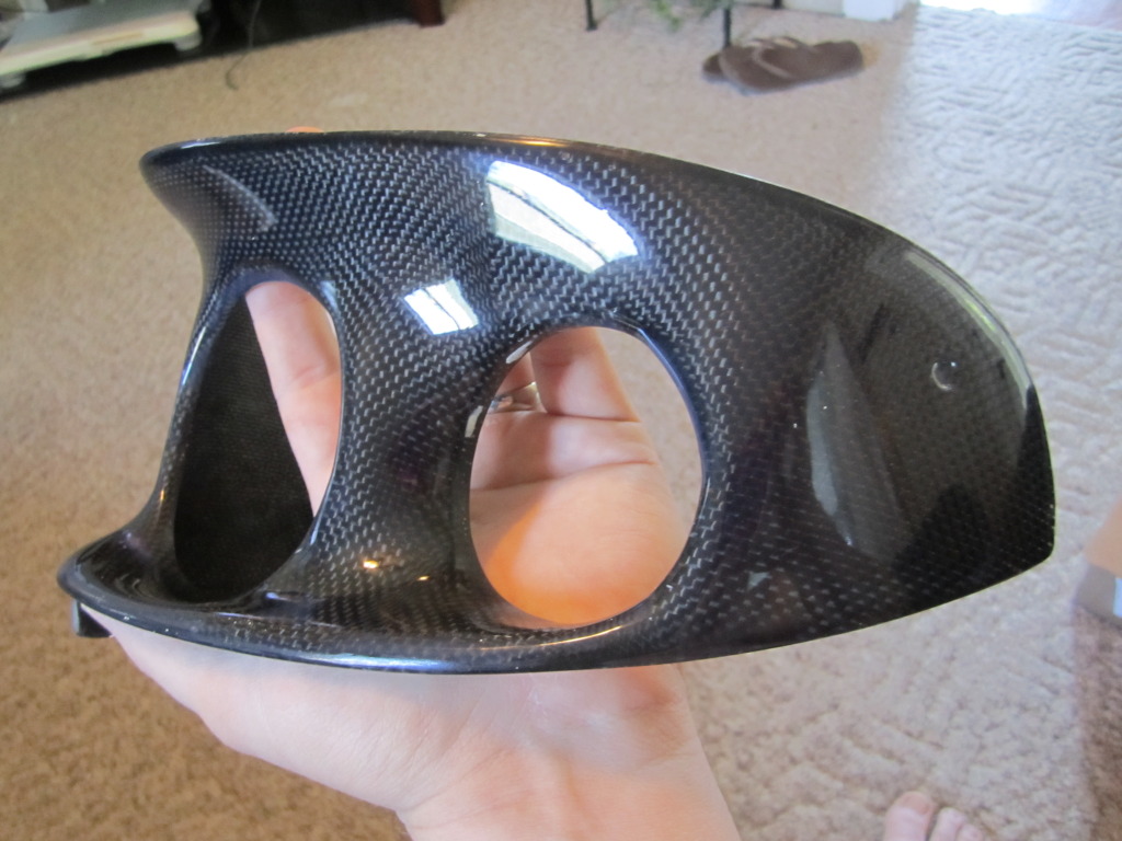
The shroud will not be offered in carbon, these are one-offs. Also they will have a primer finish, allowing a the owner to paint them which ever color they would like.
there are a few things that will need to be done before final install. The trailing edges of the shroud (near where the screws that hold on the stock shroud) are approximately 1/8 inch longer than necessary and will need to be sanded shorter to fit (on most). I chose to leave the small excess here to leave room for variation between cars.
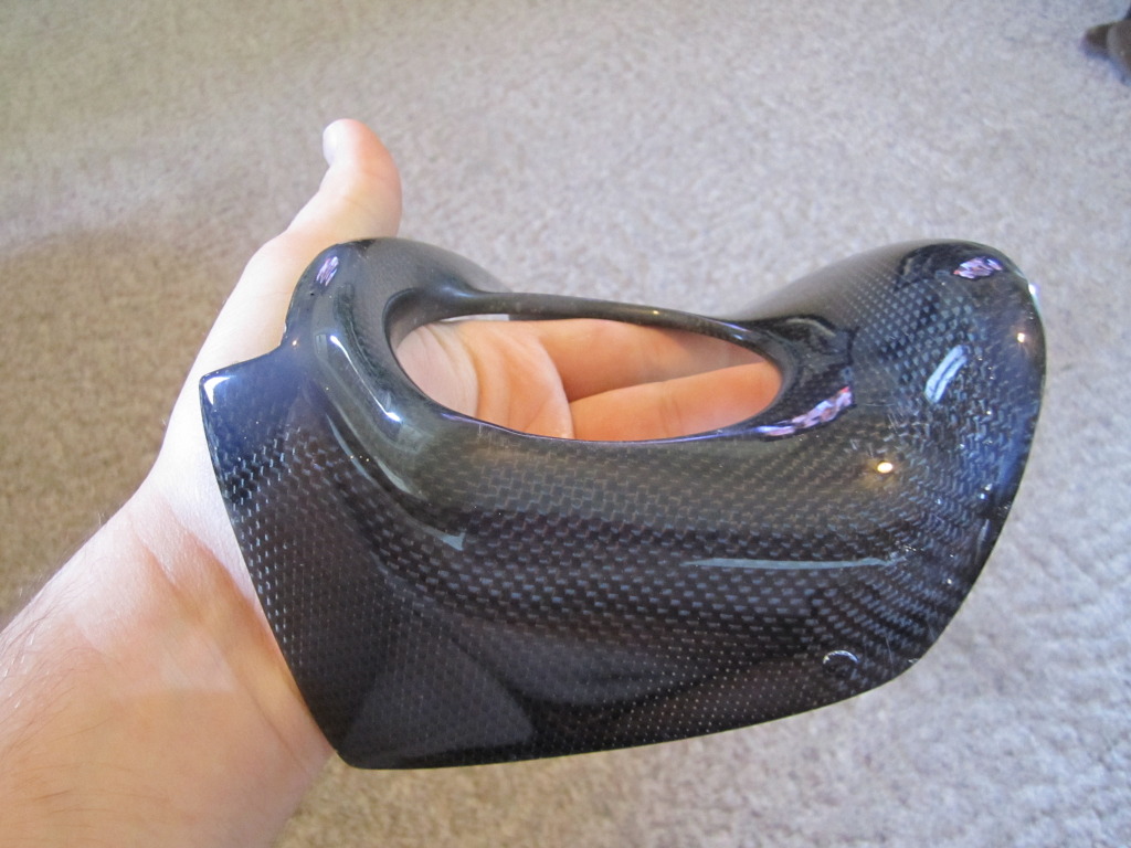
additionally holes will need to be drilled to secure the shroud (in the same manner and location as the stock shroud). again the choice to not have the holes pre-drilled, allows for variation between cars. there are marks that show the general location.
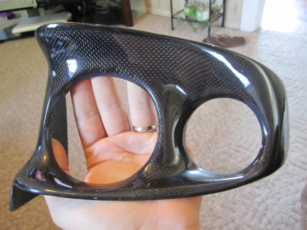
finally, button everything up and enjoy a safer drive.
there are a few things that will need to be done before final install. The trailing edges of the shroud (near where the screws that hold on the stock shroud) are approximately 1/8 inch longer than necessary and will need to be sanded shorter to fit (on most). I chose to leave the small excess here to leave room for variation between cars.
additionally holes will need to be drilled to secure the shroud (in the same manner and location as the stock shroud). again the choice to not have the holes pre-drilled, allows for variation between cars. there are marks that show the general location.


finally, button everything up and enjoy a safer drive.
04-26-13, 06:41 AM
#5
Junior Member

Join Date: Apr 2010
Location: Waterlooville UK
Posts: 31
Likes: 0
Received 0 Likes
on
0 Posts
Along with probably many others I should think, I have been waiting for this thread to appear after access to the original 'FD Sleepy Eye HID Conversion' somehow disappeared, (assumedly by mod action?)
Anyway Dan, I for one appreciate your on going efforts and can't wait for the finished product to go up for sale.
As stated on the other thread I am interested in the hardware parts, as I already have the required European lamps from previously failed attempts at doing this kind of thing
Anyway Dan, I for one appreciate your on going efforts and can't wait for the finished product to go up for sale.
As stated on the other thread I am interested in the hardware parts, as I already have the required European lamps from previously failed attempts at doing this kind of thing
Trending Topics
 05-07-13, 11:23 AM
#16
Friendly stalker
Looks awesome - you realise of course by posting the CF one offs that you have, that everyone is going to be asking 'Well, how much WOULD you charge to make them for me in CF?' lol.


 but given how long it has been so to get to this point; the question is quite fair