When you click on links to various merchants on this site and make a purchase, this can result in this site earning a commission. Affiliate programs and affiliations include, but are not limited to, the eBay Partner Network.
I'll start off by clarifying that this is for an REW swapped Rx8. A bit of background: I'm seeing excessive fuel at throttle tip-in/let-off and on decel (yes we've tried to address this via tuning). My spark plugs are carboning up after very short mileage and my exhaust tip has become black with carbon as well. If I do not turn fuel cut on during decel I will be pouring black smoke and often flames out the tailpipe with my AEM AFR gauge pegged at 10.0 until I get below ~3500 rpm where it will then roughly hold target AFR.
I have a new set of ID1050X's to try in replacement of my current ID1000's in the primary spot. Injectors have all been tested and cleaned by 2 different shops and they have come back as perfectly fine so I'm not confident that new injectors is going to solve this. This has led me into the rabbit hole of diving into checking my wiring to the injectors/ECU; I'm seeing what I believe to be some oddities but hoping someone with more electrical experience can help me figure out if I'm seeing issues or not.
The following values are roughly the same for all 4 injectors (while performing this testing all injectors are NOT plugged in to the harness):
As expected I'm seeing switched +12v on the supply pin of my harness injector connector. When I measure voltage from the ECU/grounding pin of the injector connector I am reading +1.5-4v (this seems to slowly climb as 12v switched is left on). I'm not incorrect in thinking I should be seeing 0v here since the ECU should not be trying to fire the injector? To see if maybe this was a harness issue I tested voltage directly on the pin at the back of the ECU and can confirm I am seeing this same voltage here too.
When I measure voltage across the two pins I am measuring the difference between the ECU pin and the voltage supply pin. ie. 12.2v supply - 2v from ECU pin = 10.2v across injector connector. Should this voltage not be 0v as well since it should be a broken circuit as the ECU is not triggering the injector??
To add to the complexity of this issue; when I disconnect connector 5 from my ECU (which doesn't appear to have any relation to injectors at all) I will then read 0v on my ECU/grounding pins for the injectors. I still get 12v switched supply to the injector and of course across the connector I now read 12.2v - 0v = 12.2v (I would still expect the voltage across the connector to be 0v???).
Are my assumptions above correct? Am I seeing something out of the ordinary or is this something normal to see with Adaptronic? Am I seeing some sort of unwanted voltage bleed over to my injector pins from something on connector 5 through the ECU?? What do I need to dig into next?
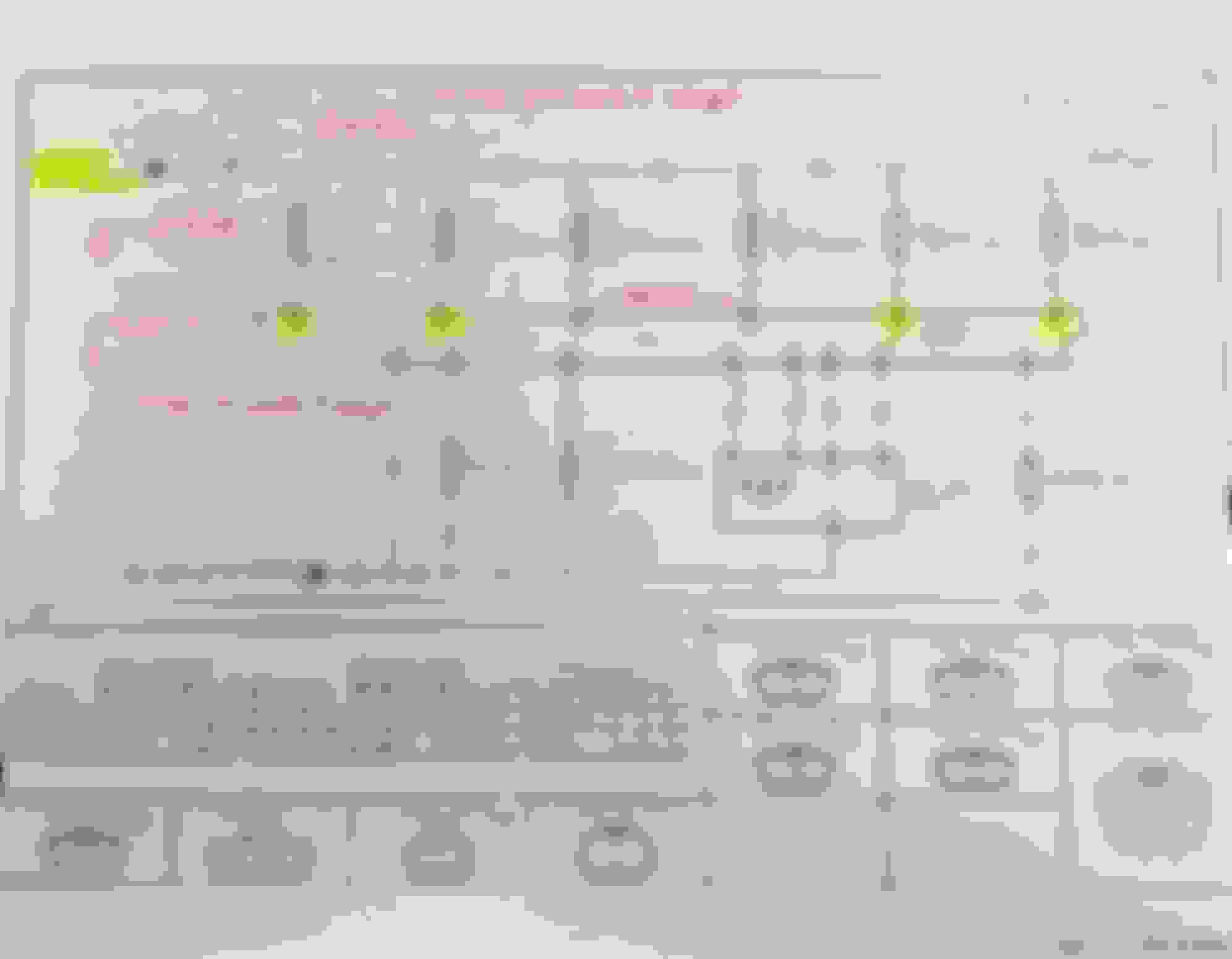
Please see Adaptronic Pinout Below for reference. I've also included a sketch just to summarize what I am seeing with my multimeter for those who are more visually inclined. I've done a ton of probing and investigating over the past few nights so if there is anything else someone would like to know just ask, I likely already have the info or will happily get it. I have all the electrical diagrams from FSM available as well.
What I'm reading via multimeter:
ECU Pinout:
Last edited by RotaryMachineRx; 04-09-24 at 12:35 PM.
Noticed primary injectors (secondaries don’t do this), are firing when I key on ignition (12v switched). I’m assuming this is a prime pulse but my understanding from HP Academy is that this should only pulse when RPM is detected (ie cranking). This explains the smell of raw fuel I get in my garage if I just key ignition on. With 50+ psi in the rails while fuel pump is priming this is likely dumping a fair amount of fuel into the engine, even when I’m not trying to start it. I’m not sure yet how this relates to the fuel dump we’re seeing on decel and throttle tip in/let-off or if this relates to the smell of raw fuel I get the next day in my garage after I park the car from driving (no fuel leaks anywhere). When I disconnect connector 5 from the Adaptronic the "prime pulse" with ignition key-on no longer happens. Also see my above video of the Eugene injector diagnostic tool and how it changes with connector 5 connected/disconnected to the ECU (Yellow is supply voltage, red is injector current, and purple is injector voltage). I've repeated this with both my original ID1000's plugged in as well as the brand new ID1050x's plugged in.
Last edited by RotaryMachineRx; 04-09-24 at 12:47 PM.
Drop the adaptronic. With no support from vendor there is no way to properly test the electrical components in the ECU to verify it is functioning correctly. I was having very odd injector issues with my old adaptronic after it worked well for years. After verifying the wiring and replacing it several times and replacing the injectors the only thing left was the ECU. Which after being changed to the haltech resolved my secondary staging issue which I used to never have. Sadly I could not send the adaptronic in to be tested by the vendor as no support was available. Just my 2c
I'm not far from this point.... I do however want to continue on this deep dive a bit more to ensure there isn't something wiring that is messaging things up. Not only has this been a tremendous learning opportunity (and continues to be so); but I just don't have the funds to drop on a new ECU and modified harness to accommodate it at the moment
Pin 2M should be 12.2V (or whatever the battery voltage is) when the injector is plugged in and the ECU is not trying to activate the injector. The voltage measurement at that pin isn't critical when the injector is unplugged, anything between 0V - 12V could be acceptable depending how the circuit is designed. In your first video, there isn't any fuel pressure so it's hard to tell if the injector is doing a short pulse or staying open the entire time the ignition is on. Does pin 2M measure 0V the entire time the ignition is on, and then the injector clicks closed when you unplug it or turn the ignition off?
The ECU triggers the injectors by connecting them to ground. This is a very brief pulse when the engine is running, probably around 1ms - 5ms (0.010 - 0.005 seconds) at idle, far too short to see as 0V on your multimeter. In your second video (eugene test) the purple trace shows a waveform suggesting the pin voltage is 12V when the ECU is not trying to activate the injector and then pulled down to 0V when it activates it. The yellow trace appears to show the voltage measured at one of the 12V supply pins, although I might be misinterpreting because I'm surprised to see the yellow trace (12V supply measurement?) drop low after the purple trace (injector voltage) goes high. If you have a test light it should flash the test light each time the injector fires. ScannerDanner is a good youtube channel for automotive electrical troubleshooting.
If your measurements are accurate and there really is 2V at pin 2M with the injector plugged in, I suspect you have either a partial short to ground in the harness (the injector signal wire 2M could be crushed or pinched or sliced and the copper part also touching the engine block or chassis or a ground wire) or the ECU itself is malfunctioning. Injector circuits will experience brief voltage spikes above 30V every time the injector closes, if the Adaptronic hardware wasn't designed to tolerate those spikes it's possible for a driver circuit like that to work for a few years and then fail eventually. It's hard to predict the exact failure mode, but failed driver circuits could act as partial shorts to ground. If you are able to safely depin that wire from the connector near the ECU, it might be useful to know the voltage measurement at both sides (near the injector, at the wire, and at the ECU.
There might be an argument for priming the fuel injector each time the ignition key turns on, but I wouldn't do that for an aftermarket ECU. Some factory ECUs might do that to assist the engine starting quickly, but they likely have logic to avoid firing the injector too often if you do something wacky like key on / off/ on / off many times before cranking the engine. If the Adaptronic adds priming fuel every single time the key turns on, I would disable that feature if the software allows. The reason to add prime fuel before the engine spins is it might help the engine start more quickly. That can be super useful for a daily driver that needs to start even when the battery is discharged and unable to spin the starter for more than a few seconds. Personally I'm not interested in my rotary engine firing up immediately after I hit the starter, because my ECU datalogs show the engine takes a few seconds to build oil pressure when cranking.
Pin 2M should be 12.2V (or whatever the battery voltage is) when the injector is plugged in and the ECU is not trying to activate the injector. The voltage measurement at that pin isn't critical when the injector is unplugged, anything between 0V - 12V could be acceptable depending how the circuit is designed. In your first video, there isn't any fuel pressure so it's hard to tell if the injector is doing a short pulse or staying open the entire time the ignition is on. Does pin 2M measure 0V the entire time the ignition is on, and then the injector clicks closed when you unplug it or turn the ignition off?
The ECU triggers the injectors by connecting them to ground. This is a very brief pulse when the engine is running, probably around 1ms - 5ms (0.010 - 0.005 seconds) at idle, far too short to see as 0V on your multimeter. In your second video (eugene test) the purple trace shows a waveform suggesting the pin voltage is 12V when the ECU is not trying to activate the injector and then pulled down to 0V when it activates it. The yellow trace appears to show the voltage measured at one of the 12V supply pins, although I might be misinterpreting because I'm surprised to see the yellow trace (12V supply measurement?) drop low after the purple trace (injector voltage) goes high. If you have a test light it should flash the test light each time the injector fires. ScannerDanner is a good youtube channel for automotive electrical troubleshooting. https://www.youtube.com/watch?v=kQUtAs-VrDY
If your measurements are accurate and there really is 2V at pin 2M with the injector plugged in, I suspect you have either a partial short to ground in the harness (the injector signal wire 2M could be crushed or pinched or sliced and the copper part also touching the engine block or chassis or a ground wire) or the ECU itself is malfunctioning. Injector circuits will experience brief voltage spikes above 30V every time the injector closes, if the Adaptronic hardware wasn't designed to tolerate those spikes it's possible for a driver circuit like that to work for a few years and then fail eventually. It's hard to predict the exact failure mode, but failed driver circuits could act as partial shorts to ground. If you are able to safely depin that wire from the connector near the ECU, it might be useful to know the voltage measurement at both sides (near the injector, at the wire, and at the ECU.
There might be an argument for priming the fuel injector each time the ignition key turns on, but I wouldn't do that for an aftermarket ECU. Some factory ECUs might do that to assist the engine starting quickly, but they likely have logic to avoid firing the injector too often if you do something wacky like key on / off/ on / off many times before cranking the engine. If the Adaptronic adds priming fuel every single time the key turns on, I would disable that feature if the software allows.
I'm going to respond to each paragraph here:
1. Okay, I was thinking it should read 0V rather than matching the supply voltage. I will plug an injector back in and measure the voltage from the back of the ECU connector while everything is connected and keyed-on and see what that reads. In my video the injector is clicking open then shutting again (ie pulsing). It is not staying open, in person you can see the pindle open then close with the clicking noise; we also grabbed a slow motion video to confirm. When I turn off the ignition with injector plugged in it does nothing, reaffirming that it is just an injector pulse when 12V switched is keyed on only. I will need to confirm voltages from the back of the ECU connector while everything is all connected. To date I have just been measuring at the ECU with the harness connector disconnected or at the injector connector with the injector disconnected.
2. "The ECU triggers the injectors by connecting them to ground."This is why I was anticipating seeing 0V at Pin 2M while the injector is not firing, but of course I was thinking about this as an open circuit with the injector disconnected. In regards to the video of the graph, I'm following your explanation and that makes sense. Yes the injector voltage spikes off the chart when current drops (as injector closes) as you indicate; the supply voltage (yellow) does have a small spike (roughly 0.5 to 1V) while the injector voltage is also spiking and current is dropping, but then it drops down to zero at the same time injector voltage and current get to zero (see screen shot below for a more clear view). This is with connector 5 plugged into my ECU. If I disconnect connector 5 the graph looks the same except the yellow supply voltage is at zero (or fractionally above zero) the entire time. In both scenarios I can hear the injector click, but I have not tried with a test light (will give this a try to confirm). X-Axis indicates this is all happening in just over 3.5ms from start of diagnostic to end.
Diagnostic graph with all ECU connectors plugged in (from you description above this seems to indicate injectors are firing as intended during this diagnostic mode?):
3. As mentioned I have not measured with the injector connected, so that is my obvious next step. This fueling issue, although masked by other issues that arise during a significant overhaul like this, made it not immediately known, but I believe has been present since day one. I'm not sure it will be an indication of failure over time rather than indication of a fault from the beginning, trivial I know, but figured I'd state it anyways lol. "If you are able to safely depin that wire from the connector near the ECU, it might be useful to know the voltage measurement at both sides (near the injector, at the wire, and at the ECU." I can easily de-pin 2M from my harness and grab measurements. I just want to confirm that I am 100% following what you mean here though; you mean to measure the injector connector voltage, voltage at the de-pinned 2M pin removed from the ECU connector, and at the 2M pin on the ECU itself, all with 12V switched powered on and the injector connected?
3b. "If your measurements are accurate and there really is 2V at pin 2M with the injector plugged in, I suspect you have either a partial short to ground in the harness (the injector signal wire 2M could be crushed or pinched or sliced and the copper part also touching the engine block or chassis or a ground wire) or the ECU itself is malfunctioning." This is ultimately what I'm trying to determine when I started this whole diagnostic. I'm not sure how good of an indicator the following would be, but with the injector disconnected, I did not measure any continuity to ground under any circumstance when measuring from the injector connector through pin 2M to chassis or engine block. My during my initial analysis hopes where I would see continuity and realize I had some sort of grounding issue, unfortunately was not the case.
4. I'll have to confirm if this is a feature that can be turned on or off. Watching the HP Academy course with the Adpatronic wired up to their RX7, he briefly mentions it on his "259 Cold Start Tuning - Adaptronic" video. His exact words are "There are two other tables here that I've mentioned, we start with our prime gain. So basically this is a priming amount, we can see that this table is actually set up essentially for flex fuel here so it's dependent on our ethanol content, we're on pump gas here so we are at 0% ethanol. But this is an initial prime pulse that is delivered as soon as the ECU basically sees any RPM activity from the cam angle sensor." Since I don't have cam angle, I would assume it would look for trigger wheel activity, but maybe I'm wrong in assuming this. He goes on more but it's just as you say, a multiplier to the fuel table to basically wet the walls prior to engine firing up. "but they likely have logic to avoid firing the injector too often if you do something wacky like key on / off/ on / off many times before cranking the engine" - this is something I'll need to test, it was doing it every single time we were turning ignition switch on but we didn't do it repetitively in short duration; typically about 15-30 seconds between key-on cycles if I was to guess. I would imagine I can set this table to 0 and the prime pulsing should stop, I'll have to play around.
Wow, thank you so much Scott for this in-depth response, not only has it given me some direction for testing but provided me some valuable insights to how this system should be working; I really appreciate that sharing of knowledge!!
Last edited by RotaryMachineRx; 04-10-24 at 04:28 PM.
1. The injector needs 12V at one side and ground at the other side for it to fire. Imagine if you had only one wire from the injector connected to the battery 12V post, and the other wire of the injector not connected to anything. Without the second injector wire connected to ground, nothing happens. If you measured that second (floating) wire that doesn't connect to anything, you would see 12V (same voltage on both wires). The reason the car is wired this way is because it's cheaper to build a driver circuit that is either (open) or (connected to ground), than to build a driver circuit that is (open) or (connected to 12V).
2. I think I'm misinterpreting the chart, but I would expect the yellow trace to stay at 12V at 4.0ms and 4.5 ms because the supply voltage is probably not dropping to zero volts.
3. Yes, exactly. If you disconnect the ECU from the harness, then your voltage measurements on the harness side will help show if there's a short to ground in the harness. And your voltage measurements on the ECU side might help show if there's a short to ground (or partial short to ground) in the ECU.
4. It's also possible for a driver circuit to briefly activate when the key turns on, before the processor finishes its power-up sequence and begins calculating whether the injector pin should be on or off. It's possible to design the driver circuit and/or program a processor in ways that would avoid this, but I wouldn't be surprised to see some of the outputs get triggered briefly at key-on in a first-generation aftermarket ECU. Second or third generation products tend to fix that behavior, after a few customers call in and complain that triggering a nitrous solenoid and/or ignition coil output briefly at power-up caused their intake manifold to explode. This is a completely hypothetical situation, not at all influenced by years of experience helping build automotive aftermarket electronics.
Apologies for the length of time it has taken for me to respond back to this thread, was hoping to get this all done faster but that's life.
I went down the rabbit hole and made what I can only hope are some significant changes to grounding. While in the midst of this I also removed my engine harness, pulled it apart, removed some abandoned connectors (factory ignition) and cleaned the whole thing up. I also continuity tested every connector on the harness and mapped it out for myself... comparing this to the Adaptronic pinout, there were no suprises here and it all matched up as it should be. I also cut out a few solders that, although were likely fine, I didn't like and replaced them with dual wall, adhesive lined, heat shrinkable crimps which I think are better suited for under the hood.
I did find that my Hall Effect CAS wiring is not true shielded wire from the sensor connector on the block back to the main harness trunk. It did however find a bare copper wire wrapped helically around the signal wires which was spliced back into the shielded factory wiring sheath that runs through the harness trunk back to the ECU. This bare copper had continuity all the way back to my ECU where I could find the shield ground, grounded to my ECU on a sensor ground pin. Not knowing how effective of shielding this is or not (couldn't find any real examples of this on google) I then scoured through every log I had to see if I had any trigger count errors in any of my logs. There worse I could find in a coupe logs was 1 or 2 errors with most logs having a 0 count; not to mention a timing light as always read true; so I don't believe this to be an issue.
Grounding wise I removed all my original 4awg grounding. This was run from the battery up to a lug on the transmission. From here there was a 4awg cable from that lug to a less than ideal "chassis" location that was actually on the subframe and not the chassis itself. The block then had a 10awg wire from the rear housing to the subframe location. Pictured below.
Now what I've done is moved my ECU grounds to a cleaned off better chassis location than where it was from factory. I then ran a 4awg ground from the chassis back to a star point on my rear housing. I then pulled a new 2awg cable from the star point back to my battery negative. Anything else that was grounded to the block is now grounded to this star point as well except for my AEM IGN-1A grounds (Pin C) which are grounded to their respective housing. I left a 10awg strap between housing 1 and 2 grounding points which was likely unnecessary but I already had this from prior. I then separated Pin B from the Rywire harness which was grounded via the same ring terminal as Pin C on each housing, and ran dedicated wires for front and rear coils (Pin B) to a sensor ground pin directly on my ECU. I did the same for Pin D in the past and ran this directly back to my battery negative. The AEM coils are now 100% grounded as per the AEM wiring diagram.
After doing all this I then ran Eugene diagnostics to confirm that the Adaptronic is firing correctly each of my injectors as well as each one of my ignition coils as commanded. This was a 100% pass.
I then probed each pin on my harness side ECU 5 connector (while it was unplugged from ECU) with 12V switched on to confirm I wasn't getting any strange voltages on any of the pins it should not have been. Everything there seems to check out as expected.
As per Scott's previous advice, I tested voltage at the injector and at the ECU injector trigger pin on the harness connector. With an injector plugged in I read 12.2v (same as battery voltage) on the harness connector whether it is plugged into the ECU or not. When ECU connector is unplugged I was reading 1.1V on the back of the ECU itself (similar to before); but with injector plugged in, and harness plugged into the ECU this voltage doesn't seem to matter as I see battery voltage as expected.
I'm now just about to put the new ID1050x primary injectors in, re-install my fuel rails, put UIM back on and smoke test for any vacuum/boost leaks. Once I have this back together I need adjust my ECU map for the new injectors and burn off this older fuel in the tank (6 months old now). Then I have a tuning session scheduled with my tuner to see if any of this has made any changes to the issues I was seeing..... If not, I'll be heavily contemplating going for an Elite 1500.
Last edited by RotaryMachineRx; 06-03-24 at 10:07 PM.
 04-09-24, 12:29 PM