
4-Rotor FC Build

 02-06-12, 09:05 PM
#327
Moderator
iTrader: (3)
Join Date: Mar 2001
Location: https://www2.mazda.com/en/100th/
Posts: 31,119
Received 2,786 Likes
on
1,972 Posts
Your totally right, I was thinking the same thing myself. The way it is now isn't that weak, there are 3x 2" wide brackets made out of 1/8" stainless steel. I did some calculations and they should hold up without budging a lot. I can lift the engine holding that fuel rail. But I really really wouldn't want a fuel leak right above a really hot exhaust with this engine, so I'm going to make some reinforcements for peace of mind.
02-07-12, 11:43 AM
#330
Senior Member

 02-07-12, 06:11 PM
#332
 .
.Mmmh is it just me or is the middle plate an other plate. The intake is higher then the rest.
@ts: why you don't change the front so you can run drysump, can be that hard if you make your own two piece excentric axle.
Oeeeh nice trigger wheel, but I miss something, jup the space out (or how you call it) for the TDC of rotor 1
@ts: why you don't change the front so you can run drysump, can be that hard if you make your own two piece excentric axle.
Oeeeh nice trigger wheel, but I miss something, jup the space out (or how you call it) for the TDC of rotor 1
Don't want to go drysump, lots of work and money involved and this is going to be a mostly street driven car so I don't see the need for it.
Can't make the timing marks in the triggerwheel yet. Most accurate way of doing that would be to mock up the engine with the 4-rotor e-shaft, set each rotor at TDC and then make marking points. E-shaft isn't done yet so that will have to wait.

Should be pretty much bulletproof

And messed around with the oilpan, I dug out some spare parts and mocked up some stuff together. I'm planning to use the stock rear FC engine mounts, and then add another mount in the front area of the engine to reduce the load on the rear mounts. This leaves the rear part of the engine and the entire transmission / driveline in the stock position. I'm also planning to use an oil pan just like a normal engine has.
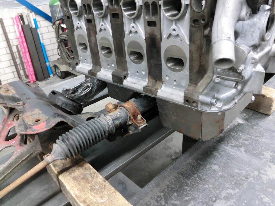
Mocking up

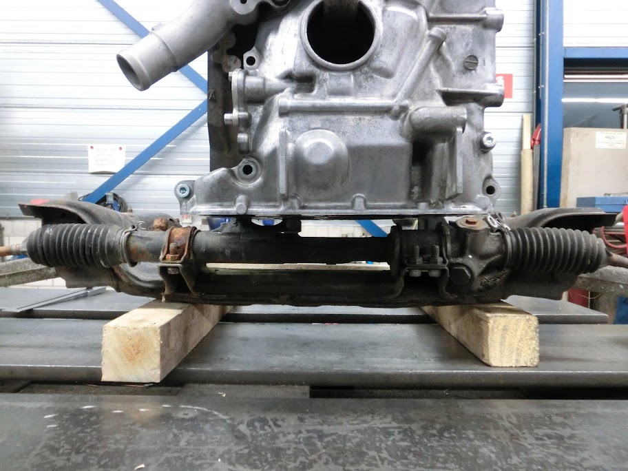
Yep, that steering rack is in the way.
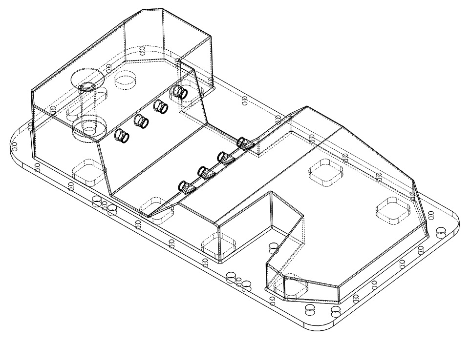
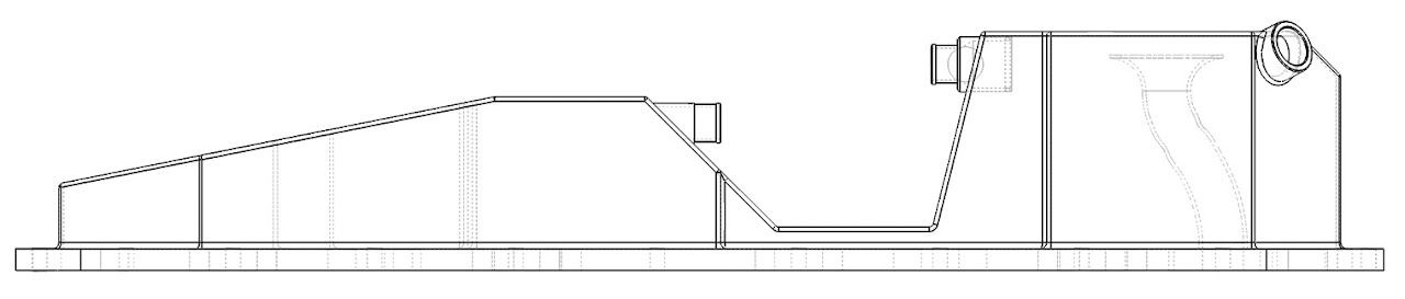
So I took some measurements and gave it some thought. The steering rack basically goes straight through the oil pan, so I tried designing an oilpan with a cutout for the rack. Good thing about this is that the cutout will act like a baffle which is good for a very long pan like this. Downside is that oil needs to be able to get from the rear part of the sump to the front part. To solve this I added some tubes where hoses will go. The hoses will run between the subframe and the steering rack. Maybe I can make some one way ball check valves in there to further help with baffling, like they do here:
http://www.billetfab.com/pans.htm
I also tried keeping the topside of the pan pretty closed with a few holes for the oil to get to the sump, this helps with sloshing and adds structural integrity.
Any thoughts on this design? I could use some input here
By the way, don't pay too much attention to the oil pickup location. I just quickly added it in there, but it's too much to the front at the moment. I'm planning on placing it more to the center of the front sump.


 02-08-12, 12:51 PM
#336
Senior Member

 02-08-12, 12:54 PM
#337
ah so it's not going to be a semi dry sump setup but an actually submersed system, i like this build even better now!
and you know you have a real engine when the engine needs 4 mounts...
curious to see what you do about the pass-under lines for the rack. quick disconnect or will it be pretty well married together. i never even thought of going this route because simply of what you see in the picture as the motor virtually sits right on top of the rack making a pan system difficult. AN fittings and -10 hose would probably do and make it an easy task to get the engine out without taking the rack with it.
i might even bug you for the dimensions on the pan.
Last edited by RotaryEvolution; 02-08-12 at 01:03 PM.
02-08-12, 01:51 PM
#338
So basically I'll be moving the problem around if I start hacking the subframe / rack. Theres a safety hazard also, hacking and weakening the subframe and then placing a heavy 4-rotor engine on top of it could get ugly.
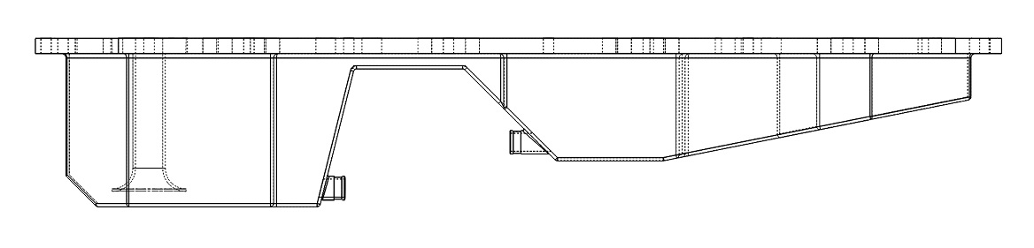
By the way, why did you slope that thin part in the middle of the oil pan?
curious to see what you do about the pass-under lines for the rack. quick disconnect or will it be pretty well married together. i never even thought of going this route because simply of what you see in the picture as the motor virtually sits right on top of the rack making a pan system difficult. AN fittings and -10 hose would probably do and make it an easy task to get the engine out without taking the rack with it.
02-08-12, 02:55 PM
#339
Moderator
iTrader: (3)
Join Date: Mar 2001
Location: https://www2.mazda.com/en/100th/
Posts: 31,119
Received 2,786 Likes
on
1,972 Posts
i dont think i have a good picture, but i have a competition oil pan in my fb, and it pretty much looks like your drawing....
in a 1st gen, its front sump, to clear the steering, but the comp pan is humped like your drawing
pic isn't great, but i think you get the idea? it seems to work really well (it doesn't leak, it doesn't hit the ground....)
BTW, NOW i would use the fuel rail to lift the motor!
in a 1st gen, its front sump, to clear the steering, but the comp pan is humped like your drawing
pic isn't great, but i think you get the idea? it seems to work really well (it doesn't leak, it doesn't hit the ground....)
BTW, NOW i would use the fuel rail to lift the motor!
02-08-12, 03:39 PM
#340
Senior Member
The slope in the middle prevents that oil is laying there, but can cool down and glides back to the front pan.
@j9fd3s: if you drain the oil you need to put the rear of the car up els you can't remove "all" the oil?
@j9fd3s: if you drain the oil you need to put the rear of the car up els you can't remove "all" the oil?
02-09-12, 05:22 PM
#342
Moderator
iTrader: (3)
Join Date: Mar 2001
Location: https://www2.mazda.com/en/100th/
Posts: 31,119
Received 2,786 Likes
on
1,972 Posts
IMO, its not a big deal, you can't drain the cooler, or the rotors either, so just change it more often
 02-12-12, 04:36 PM
#344
Started work on the oil pan
Takes some time because I'm making all the sheets myself instead of having it cut on the waterjet or something.
First thing I did was transfer my 3D model into 2D flat pattern .dxf files on the computer. I plotted those on paper using a 1:1 scale. Then manually cut out all the patterns and lay them on a piece of 2mm sheetmetal
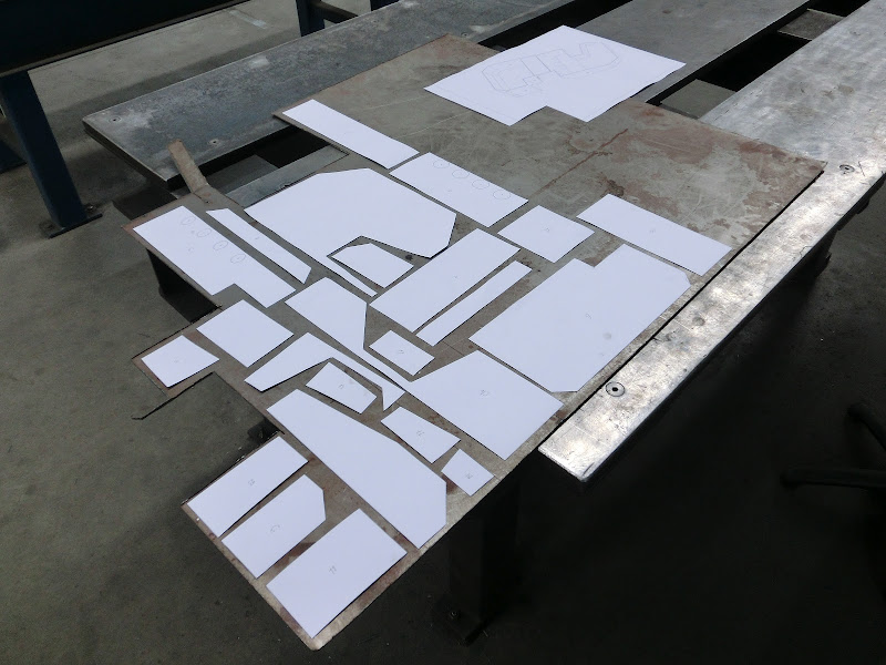
Next job was transferring the patterns into sheetmetal. I use a manual plasmacutter to roughcut every piece of sheet and keep each piece around 3-5mm's larger than the pattern all the way around. After that I mark exactly how much needs to be removed where and then fine trim everything using a beltsander. Then drill all the holes, machine out the pockets and make the needed fittings. This is time consuming, it took a day to make these parts

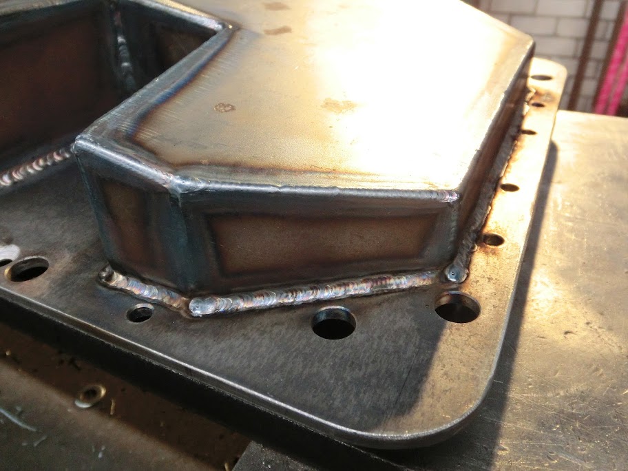
This is the fun part, tacking every part together and seeing all the parts form an oiltank

All tacked up! Next job is getting the engine, subframe and the pan together and do some fitting and checking
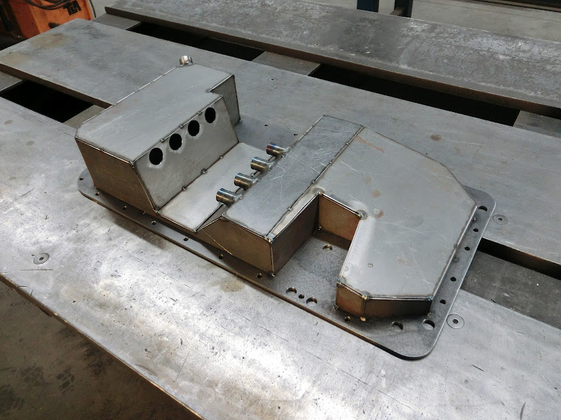

As you can see in the above pictures, I haven't added any fittings to the front part of the sump yet. That's because I'm thinking about machining fittings that hold a check valve, like this:

The open part is directed to the front sump, the smaller part is directed to the rear sump. The idea is that during normal conditions when the oil flows from the rear to the front sump everything can flow normally without any restrictions. But during hard acceleration when all the oil tries to get to the rear sump away from the oil pickup the oil flow will push the ball towards the opening, which blocks it.
Anyone have any experience with anything like this?
Takes some time because I'm making all the sheets myself instead of having it cut on the waterjet or something.
First thing I did was transfer my 3D model into 2D flat pattern .dxf files on the computer. I plotted those on paper using a 1:1 scale. Then manually cut out all the patterns and lay them on a piece of 2mm sheetmetal
Next job was transferring the patterns into sheetmetal. I use a manual plasmacutter to roughcut every piece of sheet and keep each piece around 3-5mm's larger than the pattern all the way around. After that I mark exactly how much needs to be removed where and then fine trim everything using a beltsander. Then drill all the holes, machine out the pockets and make the needed fittings. This is time consuming, it took a day to make these parts
This is the fun part, tacking every part together and seeing all the parts form an oiltank
All tacked up! Next job is getting the engine, subframe and the pan together and do some fitting and checking
As you can see in the above pictures, I haven't added any fittings to the front part of the sump yet. That's because I'm thinking about machining fittings that hold a check valve, like this:
The open part is directed to the front sump, the smaller part is directed to the rear sump. The idea is that during normal conditions when the oil flows from the rear to the front sump everything can flow normally without any restrictions. But during hard acceleration when all the oil tries to get to the rear sump away from the oil pickup the oil flow will push the ball towards the opening, which blocks it.
Anyone have any experience with anything like this?

 02-14-12, 05:03 PM
#347
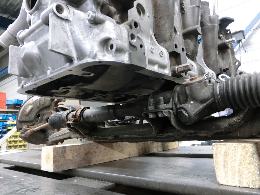
Checking fitment:
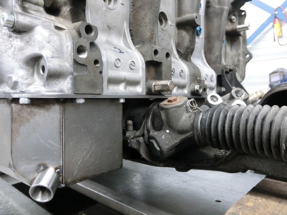
Fits pretty good. I don't know at what angle the engine is going to be when it's in the car, so I can't tell exactly how much clearance I've got, but there isn't any way to make an oil pan with more clearance. Even going dry sump isn't going to help. The first thing that touches the steering rack is the oil pan flange in the first picture. So I'm going to go with this pan design, and change the steering rack / subframe / engine mounts if I get into trouble later on. I've also looked at making some front engine mounts. I would like to mount it to the subframe, but it's hard to think of something strong, there isn't a solid way to mount something because the rack is in the way, so I'm going to wait with the front engine mounts fow now untill I can mock the engine up in the actual chassis
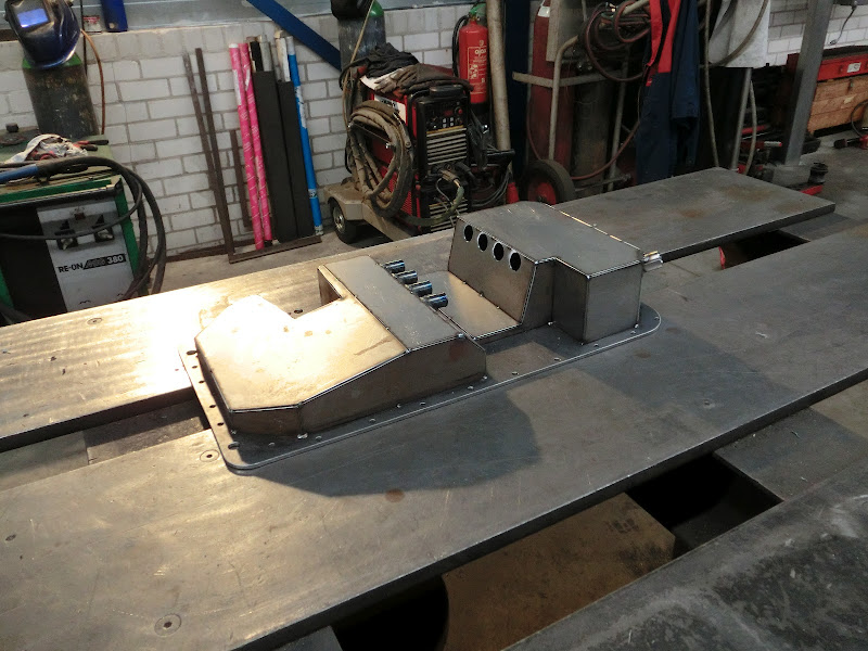
When the clearance was checked I started welding
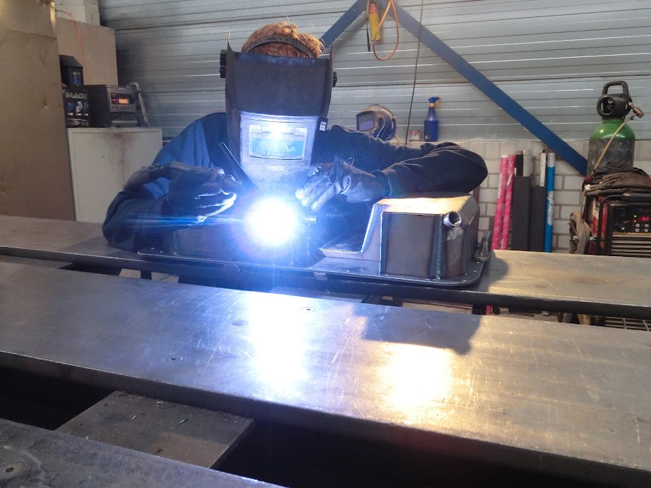

There's quite a bit of welding in this piece, took me 1,5 hours to weld. I think it turned out ok, I've bended the pan before welding, so the welding actually straightened it. Did a quick check and the flange is flat within a mm or so. I'll let the pan cool overnight and check and straighten it tomorrow when it's fully cooled. It's going to get machined flat anyway, but it's still better to get it as flat as possible before machining.
Fits pretty good. I don't know at what angle the engine is going to be when it's in the car, so I can't tell exactly how much clearance I've got, but there isn't any way to make an oil pan with more clearance. Even going dry sump isn't going to help. The first thing that touches the steering rack is the oil pan flange in the first picture. So I'm going to go with this pan design, and change the steering rack / subframe / engine mounts if I get into trouble later on. I've also looked at making some front engine mounts. I would like to mount it to the subframe, but it's hard to think of something strong, there isn't a solid way to mount something because the rack is in the way, so I'm going to wait with the front engine mounts fow now untill I can mock the engine up in the actual chassis
When the clearance was checked I started welding
There's quite a bit of welding in this piece, took me 1,5 hours to weld. I think it turned out ok, I've bended the pan before welding, so the welding actually straightened it. Did a quick check and the flange is flat within a mm or so. I'll let the pan cool overnight and check and straighten it tomorrow when it's fully cooled. It's going to get machined flat anyway, but it's still better to get it as flat as possible before machining.
