
Stock Mazda Fuel & Ignition Maps
 12-02-09 | 11:36 AM
#1
Thread Starter
watashi no shichi
iTrader: (4)
Joined: May 2005
Posts: 1,770
Likes: 6
From: San Francisco
I dont want to get too deep into this but here is what they look like from the N3A7 ROM..
I've attached the Primary Fuel map, Leading & Trailing Ignition maps.
I've attached the Primary Fuel map, Leading & Trailing Ignition maps.


Trending Topics
12-02-09 | 01:03 PM
#9
^ unlikely it is in psi... even GM does all their turbo speed density maps (GMC Syclone) in kilopascals
is the fuel map a volumetric efficiency table like GM uses? And are there boost modifier tables... again I am pretty familiar with the Syclone setup so I wonder how these compare
is the fuel map a volumetric efficiency table like GM uses? And are there boost modifier tables... again I am pretty familiar with the Syclone setup so I wonder how these compare
12-02-09 | 03:10 PM
#10
Thread Starter
watashi no shichi
iTrader: (4)
Joined: May 2005
Posts: 1,770
Likes: 6
From: San Francisco
I don't want to to get into it too much because I'm still trying to figure things out (read: learning).
Currently I don't know the scalars but I'm making highly uneducated guesses at the scales (500 - 8000 RPM & -700mmHg to +700mmHg).
At this point, I believe the maps are Load vs. RPM based. There is most likely Throttle vs. RPM maps too (tip-in,etc) but I've yet to locate them.
In conjunction with some help, I've managed to bang out an IDA Pro Processor module to aid in disassembling the firmware from the external memory chips. My goal is to build a reflashable stock "single turbo" ecu but this is a long ways off from where i stand now.
12-02-09 | 05:18 PM
#11
You will have to get some idea of how load is calculated then. On MAF based systems, it is usually measured airflow divided by rpm or measured airflow divided by some "ideal" airflow.
On the Syclones (MAP based just like the FD), fuel is calculated like this:
BPW = BPC * MAPP * T' * A/F' * VE * F33C * BLM * DFCO * DE * CLT * F77
Where:
BPW = Base Pulse Width
BPC = Base Pulse Constant Term
MAPP = Manifold Pressure Term
T' = Inverse Temperature Term
A/F' = Inverse Air Fuel Ratio Term
VE = Volumetric Efficiency Term
F33C = Battery Voltage Correction Term
BLM = Block Learn Correction Term
DFCO = Decel Fuel Cutoff Term
DE = Decel Enleanment Term
CLT = Closed Loop Correction Term
F77 = Turbo Boost Multiplier
see http://www.nwstp.com/forum/P4_section_9.asp
Factory ECU's are designed to model the engine and its potential for emissions, which explains some of the complication. Here is a list of some of the most important tables in the Syclone ECU: http://www.nwstp.com/forum/chiptable.asp
Here are the two most important fuel tables in the Syclone ECU:
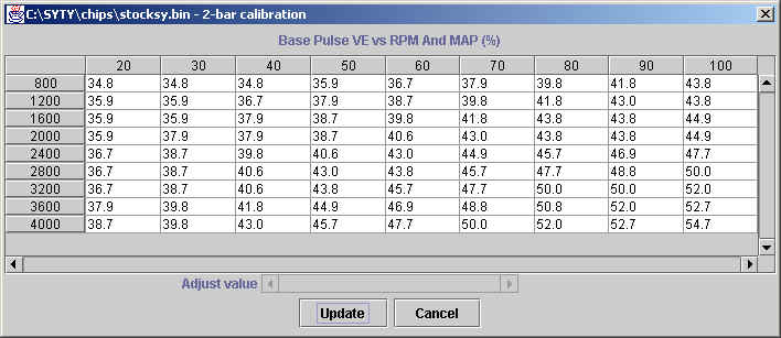
This is the basic volumetric efficiency % vs rpm vs map table. But when the Syclone goes into boost, the boost modifier trim kicks in:
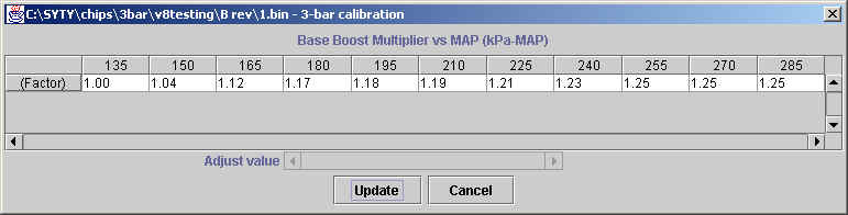
This is a two dimensional table of MAP (kilopascals absolute pressure) vs I believe a volumetric efficiency correction factor. The two tables work together along with all the other corrections. I'll see if I can dig up some stuff on the Honda internal ECU architecture. It may be closer to the FD design than the GM architecture.
Again, can you post those maps in a more readable 2 dimensional table form?
On the Syclones (MAP based just like the FD), fuel is calculated like this:
BPW = BPC * MAPP * T' * A/F' * VE * F33C * BLM * DFCO * DE * CLT * F77
Where:
BPW = Base Pulse Width
BPC = Base Pulse Constant Term
MAPP = Manifold Pressure Term
T' = Inverse Temperature Term
A/F' = Inverse Air Fuel Ratio Term
VE = Volumetric Efficiency Term
F33C = Battery Voltage Correction Term
BLM = Block Learn Correction Term
DFCO = Decel Fuel Cutoff Term
DE = Decel Enleanment Term
CLT = Closed Loop Correction Term
F77 = Turbo Boost Multiplier
see http://www.nwstp.com/forum/P4_section_9.asp
Factory ECU's are designed to model the engine and its potential for emissions, which explains some of the complication. Here is a list of some of the most important tables in the Syclone ECU: http://www.nwstp.com/forum/chiptable.asp
Here are the two most important fuel tables in the Syclone ECU:
This is the basic volumetric efficiency % vs rpm vs map table. But when the Syclone goes into boost, the boost modifier trim kicks in:
This is a two dimensional table of MAP (kilopascals absolute pressure) vs I believe a volumetric efficiency correction factor. The two tables work together along with all the other corrections. I'll see if I can dig up some stuff on the Honda internal ECU architecture. It may be closer to the FD design than the GM architecture.
Again, can you post those maps in a more readable 2 dimensional table form?
Last edited by arghx; 12-02-09 at 05:28 PM. Reason: GM tables
12-02-09 | 05:34 PM
#12
Thread Starter
watashi no shichi
iTrader: (4)
Joined: May 2005
Posts: 1,770
Likes: 6
From: San Francisco
You will have to get some idea of how load is calculated then. On MAF based systems, it is usually measured airflow divided by rpm or measured airflow divided by some "ideal" airflow.
On the Syclones (MAP based just like the FD), fuel is calculated like this:
BPW = BPC * MAPP * T' * A/F' * VE * F33C * BLM * DFCO * DE * CLT * F77
Where:
BPW = Base Pulse Width
BPC = Base Pulse Constant Term
MAPP = Manifold Pressure Term
T' = Inverse Temperature Term
A/F' = Inverse Air Fuel Ratio Term
VE = Volumetric Efficiency Term
F33C = Battery Voltage Correction Term
BLM = Block Learn Correction Term
DFCO = Decel Fuel Cutoff Term
DE = Decel Enleanment Term
CLT = Closed Loop Correction Term
F77 = Turbo Boost Multiplier
see http://www.nwstp.com/forum/P4_section_9.asp
Factory ECU's are designed to model the engine and its potential for emissions, which explains some of the complication.
Again, can you post those maps in a more readable 2 dimensional table form?
Why do I need to do this again?
Knowing what the numbers mean wont really help. Case & point would be with 90% of the "tuners" out tuning cars probably couldn't tell us how the computer figures up the fuel at the end of the routine but they "know" how to add/subtract fuel in various increments.
12-02-09 | 05:42 PM
#13
90% of the "tuners" out tuning cars probably couldn't tell us how the computer figures up the fuel at the end of the routine but they "know" how to add/subtract fuel in various increments.
On Karman vortex MAF based ECU's, if you didn't know that the tables were based on Karmann Hz you'd never understand what you were dealing with. Hertz/Karmann signals are not the same as hotwire signals.
check out other sites like romraider.com, pgmfi.org, etc
 12-02-09 | 11:05 PM
#20
Thread Starter
watashi no shichi
iTrader: (4)
Joined: May 2005
Posts: 1,770
Likes: 6
From: San Francisco
8bit (dis)Assembly Motorola baby!
I actually ended up having to write the disassembler plug-in for IDA.. It's loosely based on the 68k series but still remains a private semi-custom Denso chip.
..no hex editing done here. recompile or bust! :-)
I actually ended up having to write the disassembler plug-in for IDA.. It's loosely based on the 68k series but still remains a private semi-custom Denso chip.
..no hex editing done here. recompile or bust! :-)
Last edited by hwnd; 12-02-09 at 11:11 PM.
 12-03-09 | 09:01 AM
#22

To the OP:
The 2nd Gen Ford Probe uses the same micro. and a couple of guys on probetalk have done quite a bit of disassembly on it and are very familiar with it. Look for Mike 94PGT or ASword , they may be able to give some info you might not already have.
The 2nd Gen Ford Probe uses the same micro. and a couple of guys on probetalk have done quite a bit of disassembly on it and are very familiar with it. Look for Mike 94PGT or ASword , they may be able to give some info you might not already have.
12-03-09 | 03:32 PM
#24
Thread Starter
watashi no shichi
iTrader: (4)
Joined: May 2005
Posts: 1,770
Likes: 6
From: San Francisco
For this project to really move any further.. it'll take an EE to decipher the Denso/Toshiba processor.. My BDM isn't working with the G5 proc.. mfgr isn't really any help either.