More Proof that Fuel Pump Rewire Improves Fuel Pressure
#1
More Proof that Fuel Pump Rewire Improves Fuel Pressure
In order to prove that replacing the fuel pump wiring improves fuel pressure I have been searching for an electric fuel pressure sender to hook to my powerfc. Though I still haven't found the perfect sender yet, I have proven it indirectly! For reference the rewire in this case is to only replace the main fuel pump power wire with a 10ga wire powered through a relay. The relay is enabled whenever the fuel pump goes into high power mode (resistor bypassed). The stock fuel pump and injectors are used with no other fuel system modifications.
The conclusion comes from looking at AFR at high injector duty cycles. In the attached graph you can see clearly lower AFRs for the rewired case. When the injectors are operating at high duty cycles the stock fuel pump (and wiring) have a tough time delivering enough fuel. The result is higher than expected AFR.
Graph Definitions:
Blue = Rewired fuel pump. For the most part the AFR stays at or below the powerfc theoretical target AFR. There is a spike at 3200-3600rpm, likely because I am still using the base-mod map and haven't tuned it for my car.
Light Blue = Theoretical powerfc AFR. This calculated from the base-mod fuel maps.
Pink and Yellow - These are the control cases. Both are runs done with the stock fuel pump wiring.
Purple - Low power fuel pump case. This test was actually performed by accident. When I first did the mod, the relay enable wasn't correct. Therefore, the fuel pump was only being powered through the resistor (low power mode)! This could have been very bad if I didn't notice it.
#3
Originally Posted by scotty305
Glad to hear it, but I've got a question about your charts.
What does the horizontal axis represent? Time? Some PFC map division?
-s-
What does the horizontal axis represent? Time? Some PFC map division?
-s-
#5
Good stuff!
I did find a 0-5v fuel pressure sender somewhere once that looked pretty nice. I'll have to find it again. I've had the same thought - fuel pressure is really something that should be logged, not gauge monitored, as you have to see if the pressure ratio between boost and fuel pressure remains stable. That's much easier to see in a log than looking at a gauge.
This is definitely a mod that a lot of people don't know about. Doesn't matter how bad-*** of a fuel pump you have, if you give it crap voltage you'll sacrifice output.
Dale
#6
Each point where there is a connection offers a voltage drop. Each voltage drop has a direct relationship to resistance. Resistance is heat. One way to reduce the resistance is to solder the connection into the wire. 2) Look at the connection and make sure it is tight. 3) Upping the wire diameter will help if you rewire. However a 1 size increase is all that is needed after that it is a waste of money and time. The real improvement is the connections and how they degrade with time. The fewer the better. A lot of vibration is also very bad for connectors.
If you are interested take a volt meter and measure the voltage drop at each connection and work from there. Use some silicone grease when making the connecting to keep the connection fresh and clean. While copper oxide is conductive nothing else in the oxide family on the connector is. Hope this helps.
Doc
#7
Originally Posted by Doc-1
The real improvement is the connections and how they degrade with time. The fewer the better. A lot of vibration is also very bad for connectors.
a properly spec connector (for the enviroment) will have no damage to a connector due to vibration.
how do I say these things with confidence, I used to control specs and standards for electrical components for a 133 million dollar air vehicle. Not one solder joint on the aircraft...not one solder joint on any component I've installed on my FD (including the entire engine harness).
Trending Topics
#8
I agree with dubulup. A friend of mine has built wire harnesses for Formula Atlantic racecars, World Superbike motorcycles, and others including the Saleen S7. Their company uses crimp joints as often as possible, because a good crimp is more reliable than a good solder joint. He told me that solder is brittle and will fail more quickly when exposed to vibration. It's also much more difficult to control the quality of a solder joint, compared to using an automatic crimper which will give very repeatable results.
-s-
-s-
#9
The turbo Buick guys have been doing this for years. It guarantees full pump output when the engine needs the fuel the worst, at high RPM.
Also, another thing used is a regulator/device to run the system voltage to around 16-17 volts.
The fuel pump hotwire really works on Turbo "T"s and Grand National turbo V-6's.
I've had it in my mind to try it on the FD. But look, it's already been done!
BTW, the Walbro 255 is the pump of choice for replacement on the Buick, I see that many RX-7 vendors also have this pump available for the FD.
Originally Posted by nicad2
In order to prove that replacing the fuel pump wiring improves fuel pressure I have been searching for an electric fuel pressure sender to hook to my powerfc. Though I still haven't found the perfect sender yet, I have proven it indirectly! For reference the rewire in this case is to only replace the main fuel pump power wire with a 10ga wire powered through a relay. The relay is enabled whenever the fuel pump goes into high power mode (resistor bypassed). The stock fuel pump and injectors are used with no other fuel system modifications.
The conclusion comes from looking at AFR at high injector duty cycles. In the attached graph you can see clearly lower AFRs for the rewired case. When the injectors are operating at high duty cycles the stock fuel pump (and wiring) have a tough time delivering enough fuel. The result is higher than expected AFR.
Graph Definitions:
Blue = Rewired fuel pump. For the most part the AFR stays at or below the powerfc theoretical target AFR. There is a spike at 3200-3600rpm, likely because I am still using the base-mod map and haven't tuned it for my car.
Light Blue = Theoretical powerfc AFR. This calculated from the base-mod fuel maps.
Pink and Yellow - These are the control cases. Both are runs done with the stock fuel pump wiring.
Purple - Low power fuel pump case. This test was actually performed by accident. When I first did the mod, the relay enable wasn't correct. Therefore, the fuel pump was only being powered through the resistor (low power mode)! This could have been very bad if I didn't notice it.
The conclusion comes from looking at AFR at high injector duty cycles. In the attached graph you can see clearly lower AFRs for the rewired case. When the injectors are operating at high duty cycles the stock fuel pump (and wiring) have a tough time delivering enough fuel. The result is higher than expected AFR.
Graph Definitions:
Blue = Rewired fuel pump. For the most part the AFR stays at or below the powerfc theoretical target AFR. There is a spike at 3200-3600rpm, likely because I am still using the base-mod map and haven't tuned it for my car.
Light Blue = Theoretical powerfc AFR. This calculated from the base-mod fuel maps.
Pink and Yellow - These are the control cases. Both are runs done with the stock fuel pump wiring.
Purple - Low power fuel pump case. This test was actually performed by accident. When I first did the mod, the relay enable wasn't correct. Therefore, the fuel pump was only being powered through the resistor (low power mode)! This could have been very bad if I didn't notice it.
#10
Originally Posted by scotty305
I agree with dubulup. A friend of mine has built wire harnesses for Formula Atlantic racecars, World Superbike motorcycles, and others including the Saleen S7. Their company uses crimp joints as often as possible, because a good crimp is more reliable than a good solder joint. He told me that solder is brittle and will fail more quickly when exposed to vibration. It's also much more difficult to control the quality of a solder joint, compared to using an automatic crimper which will give very repeatable results.
-s-
-s-
#11
As said before..Turbo Buicks, Mustangs, and supra's have been doing this for years.
I can't see it hurting at all..And using MSD's (aka kennebells) boost-a-pump you can almost double your output on your pump..
I think I saw the walboro 255 doing like 388lph with the boost-a-pump setup.
I can't see it hurting at all..And using MSD's (aka kennebells) boost-a-pump you can almost double your output on your pump..
I think I saw the walboro 255 doing like 388lph with the boost-a-pump setup.
#12
Goodfalla Engine Complete
iTrader: (28)
Joined: May 2005
Posts: 3,238
Likes: 34
From: Kennewick, Washington
Originally Posted by snkydvl
As said before..Turbo Buicks, Mustangs, and supra's have been doing this for years.
I can't see it hurting at all..And using MSD's (aka kennebells) boost-a-pump you can almost double your output on your pump..
I think I saw the walboro 255 doing like 388lph with the boost-a-pump setup.
I can't see it hurting at all..And using MSD's (aka kennebells) boost-a-pump you can almost double your output on your pump..
I think I saw the walboro 255 doing like 388lph with the boost-a-pump setup.
Does this reduce the longevity on the Pump?
#13
Originally Posted by DaleClark
Good stuff!
fuel pressure is really something that should be logged, not gauge monitored, as you have to see if the pressure ratio between boost and fuel pressure remains stable. That's much easier to see in a log than looking at a gauge.
fuel pressure is really something that should be logged, not gauge monitored, as you have to see if the pressure ratio between boost and fuel pressure remains stable. That's much easier to see in a log than looking at a gauge.
#14
Originally Posted by Ledfoot
...I like to solder my crimp joints...I installed dual intank fuel pumps (poor man's mod), rewired 11 years ago, my daily driver...never had a problem with connection degrading. did the same to charging system and all custom grounding.
Personally, I prefer soldering because I've got more experience at it. I've got a pretty nice soldering iron, but haven't bought a nice crimping tool for automotive-sized wiring. I think that a good solder joint will last as long as a good crimp, but I don't have data to prove it. However, I can understand why manufacturers don't trust soldering, due to quality-control issues.
-s-
#15
so whos got a nice write-up with pics. I have a Supra pump that i installed when the stock failed. I still have the stock wiring though and that could DEFINATELY use a change. Figured it might be easier to ask the guys who recently did it, rather than start messing with all the wires to figure it out myself.
appreciate it
appreciate it
#16
Basic Instructions for Fuel Pump Rewire
The attached picture shows the service manual wiring diagram with the changes I made. My approach is different than some others in that it does not eliminate the "low speed" resistor. Also, the additional relay is controlled by the original high speed signal from the ECU (pin 1K). Therefore, the stock low and high speed behavior is maintained. This should improve fuel pump life as Mazda intended. I left out the user-specific details such as where to attach the 12V ign signal, wire guage and relay capacity, etc. How these items are chosen is really up to you and what works best for your car.
#18
Originally Posted by cewrx7r1
It still needs a new alternate chassis ground which is worth another .5volts for only six inches of wire and is the easiest change to make.
#19
Originally Posted by Monkman33
Does this reduce the longevity on the Pump?
One single pump "overclocked" is better than dual pump setup...Because if one pump dies in the middle of boosting...BOOM.
Whereas the single pump that dies, shuts the car down.
#23
Originally Posted by dubulup
you can also remove the Fuel Pump (Speed) relay...and the fuel pump resistor.
Originally Posted by dubulup
^yes they do, I've installed one...pretty neat gadget. The pump is still loud at 9V though, haha!!
#24
Originally Posted by scotty305
I think that a good solder joint will last as long as a good crimp, but I don't have data to prove it.
Solder is a poorer electrical conductor as it's mostly tin and lead. Soldered joints have higher resistance than crimped joints.
Solder is rigid and multistrand wire is not. Wires tend to fatigue and break at the solder joint from vibration and movement.
Solder requires adding power and heat to the connection which may be an issue when servicing delicate circuits.
In a hot environment solder attracts the external heat from the environment and conducts it into the electrical circuit, again raising resistance.
In a production environment soldering is more costly and labor intensive than a proper crimp.
A proper crimp is a superior connection to a soldered one in every way. I'm sure dubulup is way over my head on this one but I do know a properly crimped connection is gas tight. The crimp is so tight that no moisture etc can enter and allow corrosion to take place. I have seen the raw guts of Gulfstream jets and the amount of wiring and the amount of effort the manufacturer puts into dressing that wiring is incredible. I can't imagine what a military aircraft's must be like.
Last edited by DamonB; 08-08-06 at 11:15 AM.
#25
DamonB is correct with everything he posted...you can sort of see the splices I used with my engine harness here. Not only is the crimp gas tight ($125 tool) but there is a heat shrink cover, with glue bands that bond to the wire jacket that protects the actual crimp joint itself.

I've "read" some pumps don't like varying voltages...I just looked at it like another failure point. My pump isn't loud enough to hear...
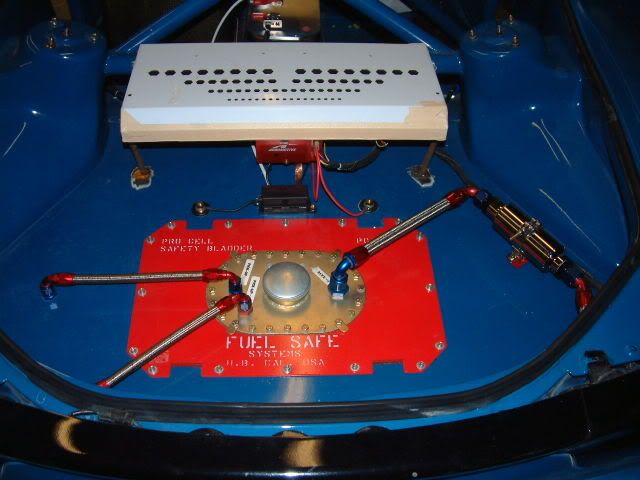
no that's not my fuel set-up...project/race/show/shop car

Originally Posted by nicad2
I still cannot find a reason to remove the fuel pump resistor. As long as you are using the high power mode (pin 1K + a relay) to bypass the resistor, I don't see a point in removing it.
Originally Posted by nicad2
Is that your fuel setup in the pics? It's wild!


