Headlight wiring mod: low beams + high beams
#1
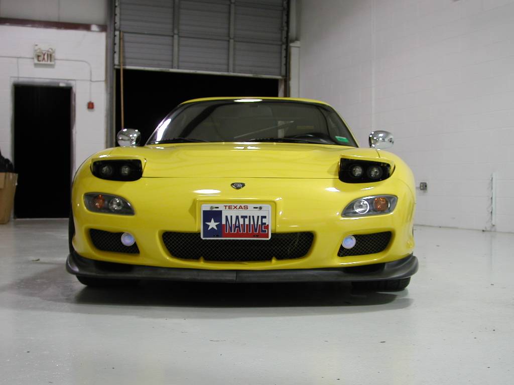
Here is how to make the stock low beams remain on when you select the high beams. This should be especially useful for people with aftermarket headlights, including bixenon or dual-beam setups (like this one).
Ideal candidate for this mod:

Procedure:
FIRST THING FIRST: DISCONNECT THE NEGATIVE BATTERY TERMINAL BEFORE DOING ELECTRICAL WORK. This includes cutting wires, or disconnecting connectors (which is usually safe, but you can never be too careful). It's worth the extra time to avoid damaging your car or yourself.
1. Area of Interest:

Remove the plastic cover from the steering column (3 screws), and the next plastic cover (4 more screws, don't forget the one near the A/C duct on the side of the dash).
2. Dash Sans Plastic:

We'll be working with the big blue connector under the steering column.
3. Big Blue Connector:

There is a clip on top (closest to the steering column). It's not very easy to see. Pinch this clip and pull the connector straight back (towards the rear of the car) gently.
4. Wires of Interest:

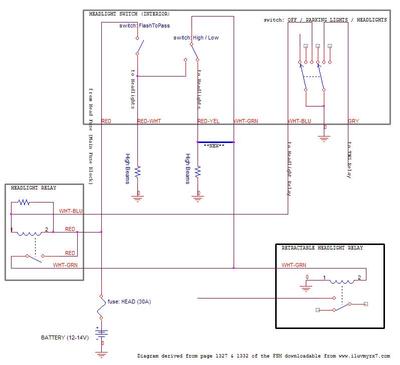
We want to connect the [white/green] wire to the [red/yellow] wire. Notice that these wires change colors on the other side of the connector. Connecting the [white/black] and [red/black] wires will give the exact same results.
5. Making Connections:

Here's how I connected them. Without cutting the wires, I carefully cut the insulation with a razor, and removed it. Then I wrapped a spare piece of single-strand wire around the two bare wires to hold them in place before soldering (twisting the spare wire with pliers will get it good and tight). Warning: these wires carry a full 12-14V and up to 30 amps of current straight from the battery to the headlight. Be sure you form a good connection or your lights will be dim.
If this is your first time soldering, practice on some junk wire before you try this on your car. Place some cardboard on the area below where you're soldering, to avoid burning the carpet with any drips.
Hope this helps,
-scott-
Ideal candidate for this mod:

Procedure:
FIRST THING FIRST: DISCONNECT THE NEGATIVE BATTERY TERMINAL BEFORE DOING ELECTRICAL WORK. This includes cutting wires, or disconnecting connectors (which is usually safe, but you can never be too careful). It's worth the extra time to avoid damaging your car or yourself.
1. Area of Interest:

Remove the plastic cover from the steering column (3 screws), and the next plastic cover (4 more screws, don't forget the one near the A/C duct on the side of the dash).
2. Dash Sans Plastic:

We'll be working with the big blue connector under the steering column.
3. Big Blue Connector:

There is a clip on top (closest to the steering column). It's not very easy to see. Pinch this clip and pull the connector straight back (towards the rear of the car) gently.
4. Wires of Interest:

We want to connect the [white/green] wire to the [red/yellow] wire. Notice that these wires change colors on the other side of the connector. Connecting the [white/black] and [red/black] wires will give the exact same results.
5. Making Connections:

Here's how I connected them. Without cutting the wires, I carefully cut the insulation with a razor, and removed it. Then I wrapped a spare piece of single-strand wire around the two bare wires to hold them in place before soldering (twisting the spare wire with pliers will get it good and tight). Warning: these wires carry a full 12-14V and up to 30 amps of current straight from the battery to the headlight. Be sure you form a good connection or your lights will be dim.
If this is your first time soldering, practice on some junk wire before you try this on your car. Place some cardboard on the area below where you're soldering, to avoid burning the carpet with any drips.
Hope this helps,
-scott-
Last edited by scotty305; 02-14-05 at 11:28 PM.
#3
Good stuff! I never thought of the trick of wrapping a piece of wire around the two wires to be soldered - that's a good one!
What headlight kit do you have on the car? Looks pretty nice!
Dale
What headlight kit do you have on the car? Looks pretty nice!
Dale
#4
Thanks Dale, that's the first time I've wrapped wires like that. At first it was to test and make sure that I was connecting the correct wires. But then it made it a lot easier to solder.
Unfortunately, that's not my car pictured above, it's Wael Al-Dasher's old car. Archives of his old website www.efini.net can still be accessed at
http://web.archive.org/web/200402081...www.efini.net/
My car is stock for now, and I'm looking into upgrading to bixenon projectors sometime this year. A couple of forum members prompted me to write this tutorial, I figure it's saving me some time down the road.
-s-
Last edited by scotty305; 02-14-05 at 11:59 PM.
#7
Originally Posted by KaiFD3S
Back to life.....Just wondering how safe it is to do this without using a relay, would'nt the load be too much and may cause an electrical fire?....Is there any other way to do this?
If I made this mod I made it with relay.
Trending Topics
#8
i think you miss labeled LOW beams in your diagram...I think I can still follow what you've done.
now you've doubled the load passing thru the headlight relay while the brights are on...I don't know what that relay is rated for, but most automotive relays are 30A.
http://www.americanautowire.com/products/
^these guys sell a 70A...or 75A relay, can't remember off the top of my head, wonder if you can retro fit that into the current headlight relay?
They also sell a relay kit to safely accomplish what you've done. Not saying your method is unsafe...you just haven't listed any specs (headlight resistance, AWG, rates etc) in your diagram and have double the load.
When the flash to pass lever is pulled, Mazda does keep the low beams on...however these was intended for a short amount of time. Have you done extended driving with your brights on? Granted you are protected by a 30A fuse...but all the insulation of that wire could burn off before your fuse blows...don't ask me how I know
Originally Posted by scotty305
Warning: these wires carry a full 12-14V and up to 30 amps of current straight from the battery to the headlight.
http://www.americanautowire.com/products/
^these guys sell a 70A...or 75A relay, can't remember off the top of my head, wonder if you can retro fit that into the current headlight relay?
They also sell a relay kit to safely accomplish what you've done. Not saying your method is unsafe...you just haven't listed any specs (headlight resistance, AWG, rates etc) in your diagram and have double the load.
When the flash to pass lever is pulled, Mazda does keep the low beams on...however these was intended for a short amount of time. Have you done extended driving with your brights on? Granted you are protected by a 30A fuse...but all the insulation of that wire could burn off before your fuse blows...don't ask me how I know

#10
i've had my miata with the moss headlight kit like this for over a year now, no problems for me. i drive a lot in the mountains at night with the brights on for over an hour at a time. i think ill do this to my fd also
#11
Originally Posted by dubulup
Now you've doubled the load passing thru the headlight relay while the brights are on...I don't know what that relay is rated for, but most automotive relays are 30A.
http://www.americanautowire.com/products/
^these guys sell a 70A...or 75A relay, can't remember off the top of my head, wonder if you can retro fit that into the current headlight relay?
They also sell a relay kit to safely accomplish what you've done. Not saying your method is unsafe...you just haven't listed any specs (headlight resistance, AWG, rates etc) in your diagram and have double the load.
When the flash to pass lever is pulled, Mazda does keep the low beams on...however these was intended for a short amount of time. Have you done extended driving with your brights on? Granted you are protected by a 30A fuse...but all the insulation of that wire could burn off before your fuse blows...don't ask me how I know

Mazda's flash-to-pass is what made me think of doing this. Before modifying anything, I drove around for 5-10 mins holding this switch. The only difference I noticed was the amount of light on the road in front of me. I've run my system like this for over a year now without any problems. I've left the brights on for hour-long drives, that's the reason I modified things in the first place.
If I was building a headlight system from scratch, I would NOT wire it up in the same manner that Mazda did. I'd put the relays much closer to the headlights, and run a smaller-gauge wire to the cabin. Thanks to Mazda's weird electrical design, we're already stuck with big wiring running into the light switch. Someday when I install aftermarket headlights with a better beam focus and cutoff, I plan to re-wire the system as well.
Regarding relays: While I don't trust every decision Mazda's engineers made, I'd be very surprised if the relay and the wiring had a lower current rating than the fuse protecting the entire system. I recently purchased a clam-on ammeter, so I'll try to measure the actual current flow on my car soon.
Also, good catch on the lack of "low beams" on the diagram. They should be the ones on the right, with the Red/Yellow wire.
-s-
Thread
Thread Starter
Forum
Replies
Last Post
82streetracer
1st Generation Specific (1979-1985)
7
08-23-15 10:28 AM


 I used needle nose vice grips lol.
