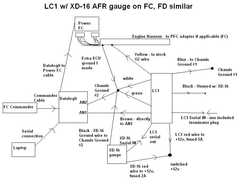
FD Defi A/F Gauge to LC-1/Datalogit Wiring
#1
The defi a/f gauge is a narrow band o2 sensor, I have already read how to convert it to accept a 0-5v signal coming from the lc-1 using a potentiometer. My question is, since the defi gauge does not have a serial out like the xd-16 gauge, where do the purple and blue wires go? How would I go about in hooking the defi gauge with my lc-1/datalogit?
#2

See the full thread I made: https://www.rx7club.com/3rd-generation-specific-1993-2002-16/my-power-fc-lc-1-datalogit-wiring-diagram-707301/
In your case, use the yellow wire coming off the LC1 to go to your Defi gauge (make sure O2 feedback is off in the PFC). You will need to use the Innovate software (Logworks I believe) to connect to your LC1 and change settings. Set the Yellow wire (analog 1) to 0-5v with whatever AFR range you want, and make sure your Defi gauge can interpret that correctly.
For analog 2, which would go to the Datalogit, set that as 0v being 9:1 and 5v being 16:1 per innovate's recommendation. Then hook it up according to that diagram (there will be slight variation because you don't have the innovate XD-16 AFR gauge). Go into your auxiliary input setup in FC-Edit and make sure it is set so that AN1's voltages correspond to your configuration on the LC1. Then set up AN2 as the ground wire using the "delta" function.
Read through that thread closely and the links that I have at the bottom. It will eventually make sense to you. You are just setting up all your grounds to eliminate any possible electrical noise, and then making sure all your displays and controllers are calibrated to the proper voltage range. All your ground wires should go to the same place except the blue wire coming off the LC1, which is for the o2 sensor heater.
#3
''For analog 2, which would go to the Datalogit, set that as 0v being 9:1 and 5v being 16:1 per innovate's recommendation. Then hook it up according to that diagram (there will be slight variation because you don't have the innovate XD-16 AFR gauge). Go into your auxiliary input setup in FC-Edit and make sure it is set so that AN1's voltages correspond to your configuration on the LC1. Then set up AN2 as the ground wire using the "delta" function.''
So if I understand this correctly, AN2 will still be ground as described in the diagram and the wiring would still be the same? The only thing I would change is the settings in FC-edit?
Also, since I do not have the XD-16 gauge, where do I put the black wire from my LC-1?
So if I understand this correctly, AN2 will still be ground as described in the diagram and the wiring would still be the same? The only thing I would change is the settings in FC-edit?
Also, since I do not have the XD-16 gauge, where do I put the black wire from my LC-1?
#4
I think the black wire goes to ground with a switch wired in parallel and an LED. I didn't want to hassle with the thing, I just got the XD-16 because it has an actual display for calibration and error codes.
All the AN2 stuff should be the same I would think. Like I said, have every ground wire for the whole setup go to the same location except the blue heater ground on the LC1.
All the AN2 stuff should be the same I would think. Like I said, have every ground wire for the whole setup go to the same location except the blue heater ground on the LC1.
Thread
Thread Starter
Forum
Replies
Last Post
rgordon1979
3rd Generation Specific (1993-2002)
40
03-15-22 01:04 PM


