When you click on links to various merchants on this site and make a purchase, this can result in this site earning a commission. Affiliate programs and affiliations include, but are not limited to, the eBay Partner Network.
To who may concern.
I had problem with the Tachometer and i swapped with a used but in very well condition Mazdaspeed cluster.
I had the Buzzer sound continuously after a long research here on the forum I found no solution.
So whats trigger the buzzer to sound continuously? only 2 things i read:
1) Low coolant
2) Over rev rpm
Since the cluster was new and the old was working without the buzzer i was thinking that was the over rev, but was much simpler to test the coolant sensor before.
Here is the magic:
I tested the coolant sensor was working, but not good. You should have electrical continuity between the coolant sensor and the ground. There wasn't but it was close i mean the differential voltage was V 11,85 instead of battery voltage of V 12,60.
This was working on the old cluster but not in this new.
I also disconnect the coolant sensor and saw that the buzzer was finally OFF and the coolant warning light ON.
I connected the coolant cable to the ground instead of the sensor and everythings is now working fine, buzzer OFF coolant warning light OFF.
So even if Your coolant warning was not giving fault before, may be the new cluster has minor tolerance in Voltage and trigger the alarm.
When attempting to diagnose a problem with the warning alarms (buzzers), it is important to follow the steps outlined in the Body Electrical Troubleshooting Manual (BEM). The section that discusses the FD's warning system is Section C2. This section covers all warning lights and sounds. Specifically, Flowchart 23 addresses the Coolant level alarm and Flowchart 24 addresses the Over-rev alarm.
It's good to hear that you found the cause of your warning alarm. However, the coolant level sensor works on sending a ground signal to the Body CPU. The sensor sends a ground signal to the Body CPU when coolant is above it. Therefore, the ground signal keeps the warning light and buzzer off. When coolant falls below the sensor, it measures an open. This open is felt at the Body CPU and triggers the alarm. The 11.85V you measured may not be the cause of the problem. The slightly lower voltage may be the result of meter inaccuracies, grounds, oxidized wires, and discharge state of the battery.
It would be more helpful to others if you could cite the reference used to diagnose your problem. Your post is helpful to a point but lacks an obvious path for others to follow. Please don't take offense; I'm suggesting that you show where and when measurements were made. That would help others understand your method of repair.
For example:
1. I followed Body Electrical Manual (BEM) Flowchart 23 for a Coolant level warning alarm that does not sound. Even though my alarm is on, this chart showed me where to measure continuity and voltage.
2. With ignition to ON, I checked +12V with the new cluster installed at the Body CPU, Pin 1C. I measured 11.85V.
3. With ignition to ON, I checked +12V at the Body CPU, Pin 1L. Again, I measured 11.85V.
4. Removed the new cluster to access one connector.
5. With ignition to ON, I checked +12V at the instrument cluster connector, Pin 3B. I measured 11.85V.
6. I verified that coolant was filled to the top of the radiator filler neck.
7. With ignition to OFF, I checked continuity at the Coolant level sensor. I disconnected the sensor from the wire harness and measured across the terminals of the sensor. With coolant level full, I measured an open (no continuity).
8. The coolant level sensor showed a bad indication. It should measure a short when coolant is above the sensor.
9. Reassembled the new instrument cluster then shorted the coolant level sensor wire (from the wire harness) to ground.
10. With ignition to ON, I observed the coolant level low light was off and the buzzer was off. This verified the suspect fault in Step 7.
Does that help draw a logical conclusion to the failed component? Again, no offense to your content. Glad to hear that your problem was the coolant level sensor!
Ok, You all right.
I'll do my best taking also some picture tomorrow.
The problem is that i found a lot of difference in pin and cable from USA manual (only manual I have). So the pin reference number don't match.
I'll see what i can do to make it as clear as possible.
Regards ;-)
Pietro
My RX7 is a 1993 FD for the Italian market (VIN: JMZFD13B200100XXX). I guess is the same in all Europe except for the UK which is RHD
Mechanically is all most the same of the USA market, may be some minor difference as bumbers, signal or similar due to law regulation.
The biggest difference I found during years are electrically, pins, cable colors, plugs...
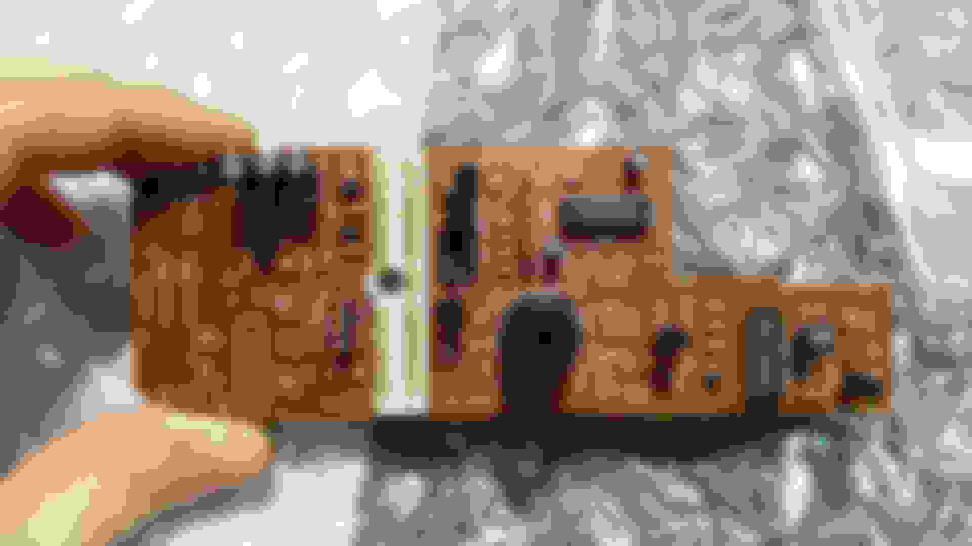
Without go far away i'll post the pdf of the 1993 USA spec of CPU n�2 and what i found on my CPU n�2
If You see the pics not only wire are different in colors and numbers, the plug is different, i have 17 wire connection instead of 20. Thats mean that also the CPU 2 is slightly different. CPU n�2 Italian market
Also in the plug connector of the cluster, a lot of wire are different in number and location, Follow and example of the connector that go back to the tacho Plug back of the Tachometer
Regards
Pietro
Last edited by pietrino; 04-20-20 at 05:07 PM.
Reason: adding regards
Wow! That is very different from the US models! Your Body CPU is physically different from the US version as well. I better understand your problem now. I'm also surprised that no manual exists for the EU market FD.
Ok, sorry for delay (consider also timezone), i Went to make a lot of picture but the problem occurred again.
So be patient, i will try to solve with some documentation for further people.
About manual: probably there was, but Mazda in Italy changed owners (dealer company) a lot of time so by now there in no chance to have this manual. Even Mazda Italia doesn't have a copy (they said this to me at least).
Do not worry about the delays. Take your time. What problem are you having? Is it with photo uploading? If you have large photos then you may need to resize it. Normally, I have good luck when the photo is resized to 1920x1080 pixels. The file size is small enough for posting and the size of the photo in the post provides good detail.
The main purpose of your post was about fixing your coolant level sensor. We can work on finding the right schematic for your Body CPU. I'm surprised that Mazda Italia does not have a copy of the FSM!
On a side note, where in Italy are you? I asked in an earlier thread but do not remember. Sorry for not remembering. How are you and your family coping with the coronavirus?
Just to info in case for Italian or European People. This is how You will find Your CPU2
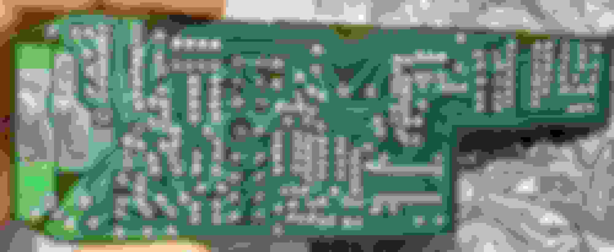
My car is a 1993 Mazda RX7 prduced in Hiroshima on february 1993 i guess the code is FD13 Vis start with JMZFD13B200100XXX CPU2 Italian (may be also European Spec) CPU 2 connected Back CPU2 of circuit Italian EU spec Side with another plug 17 pin plug (only 10 connected on my car 1993 FD manual trasmission)
Last edited by pietrino; 04-24-20 at 08:57 AM.
Reason: Adding photo and details
Well done! WOW! That looks very different from the USDM spec CPU#2 for the FD. It is very different from the FC version as well.
Thanks for sharing the different version. In fact, this may call for a separate conversation. Would you like me to make a new thread to further discuss the EU specific CPU#2? This would also help others identify a similar problem with EU spec Body CPUs.
What does the flasher CPU look like? Are there any other circuit boards in there? I know the 93 FD for the US had an "Option" connector that plugged into the Body CPU but it served no purpose. It is a connector just besides the flasher CPU connector. I believe that was an expansion plug that was never used. It was eliminated in the 94-95 FD.
P.S. While the CPU#2 is out, please inspect the solder joints for any suspected damage by leaked acid from capacitors.
Last edited by Gen2n3; 04-23-20 at 03:24 PM.
Reason: Added post script.
As another note, did the buzzer problem return? Did you verify the coolant level is full? To be thorough, I believe we should verify the over-rev alarm is working properly.
I see that you use the Knightsports ECU in your FD. Does it send a tach signal to the instrument cluster? If it does then what wire does it connect to?
As a reference, Flowchart #24 of the Body Electrical Troubleshooting Manual (BEM) has test procedures for the over-rev alarm on US models. Maybe we can find something similar?
Thanks for reply and support.
the Buzzer problem came back. But I found that the problem is the new speedometer. Before attemp to repair i have to find a deal with the seller i just bought.
The ECU is just a Stock ECU with a new chip a map so i Guess is working well, and i found the cluster wire from flowchart 24 and tested, was working good.
Thank you very much for sharing a section of this rare manual! This will help @pietrino immensely! I'm looking over the schematics to see the differences. Immediately, I noticed a 5th connector to the Instrument Cluster wire harness at C1-01. This is for the cruise control and air bag indicators. Another observation is the CPU#2 only uses 10 pins.
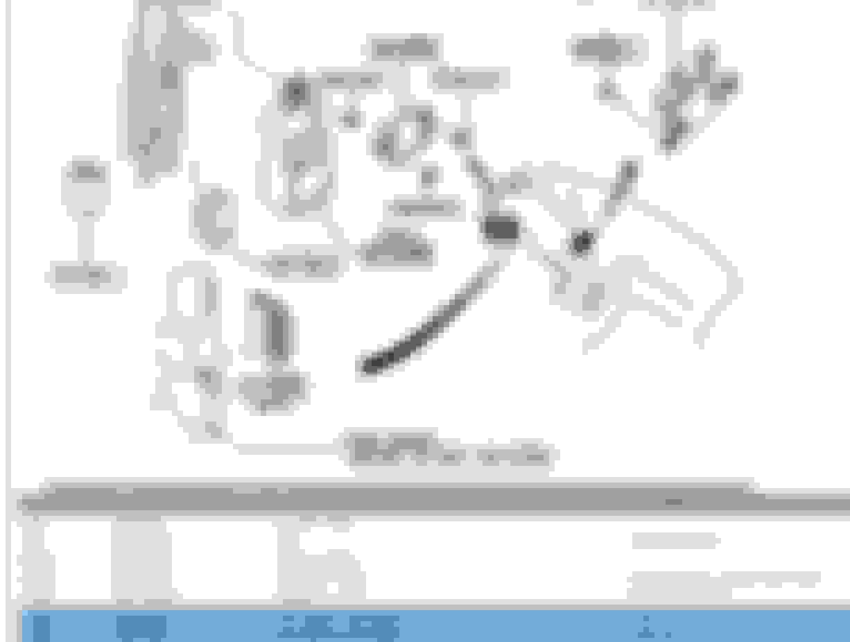
Here is the shot from the parts catalog, it is EU market, which is LHD. now that i think about it, the UK is not in the EU, so i don't know what they get. the other EU thing is that they are all manual transmissions, nobody in the EU knew how to drive an automatic in 1993!
Here is the shot from the parts catalog, it is EU market, which is LHD. now that i think about it, the UK is not in the EU, so i don't know what they get. the other EU thing is that they are all manual transmissions, nobody in the EU knew how to drive an automatic in 1993!
the USA uses an FD01, Japan uses an F100
The part number of the Mazda Italia is the same as Your picture FD13-67-560 or FD13-67-580
If you were to order a replacement Body CPU, you should verify that it is stamped FD13, like yours. Otherwise, you will get a USDM (FD01) or JDM (F100) unit. I don't believe your Body CPU is bad.
Thanks to @j9fd3s, for posting the parts catalog for the the Body CPU (CPU#2)!
LOL, nobody in the EU knew how to drive an automatic in 1993!
@pietrino, You speak and write in excellent English. How is your German? You can use the USA version of the schematic in addition to the photos provided by Zepticon. Otherwise, the Google Translate application is an excellent translator on schematics. It came in handy when I needed to read schematics written in Japanese.
Sadly, my Italian needs a lot of work! Parlo un pochissimo.
Would the UK model use the JDM spec? I helped another member with a F100 CPU#2 and he was in the UK. Then again, he may have a JDM import. I would have to double check.
If you were to order a replacement Body CPU, you should verify that it is stamped FD13, like yours. Otherwise, you will get a USDM (FD01) or JDM (F100) unit. I don't believe your Body CPU is bad.
Thanks to @j9fd3s, for posting the parts catalog for the the Body CPU (CPU#2)!
LOL, nobody in the EU knew how to drive an automatic in 1993!
Originally Posted by j9fd3s
yes, i could not get that part number to work in the normal places, but the price lists vary by region, i only have US and Japan.
I have access to online Mazda Italia spare parts catalog that work with my vin to match parts, so I can be sure when the part number is for my car.
Originally Posted by Gen2n3
This is what makes the forum awesome! Multiple people around the world who come together to help solve a problem.
@pietrino, You speak and write in excellent English. How is your German? You can use the USA version of the schematic in addition to the photos provided by Zepticon. Otherwise, the Google Translate application is an excellent translator on schematics. It came in handy when I needed to read schematics written in Japanese.
Sadly, my Italian needs a lot of work! Parlo un pochissimo.
My German is like aramaic, anyway as You said I can compare this manual with the english one or ask help at google translate. Anyway is a big big help. I had to to find continuity between many wire to understand a bit how it's work.
Thanks fo support

 04-20-20, 01:02 PM