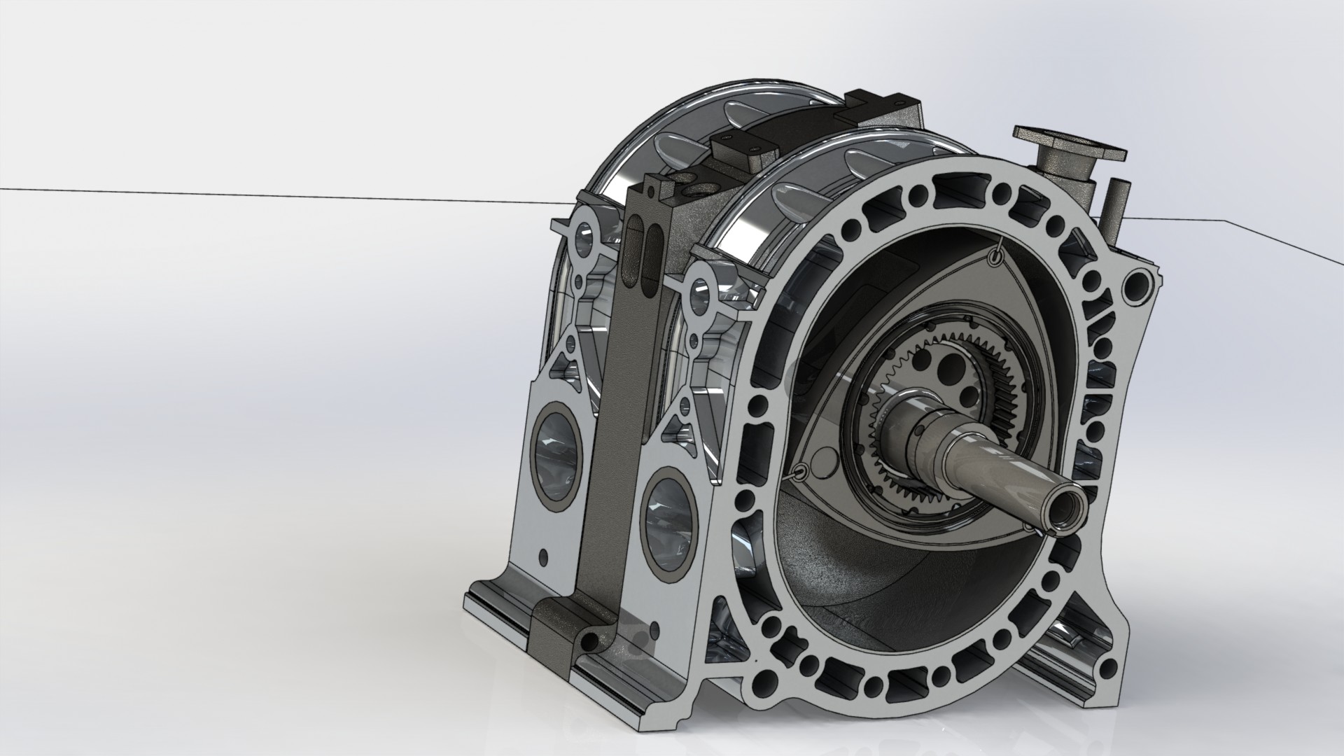
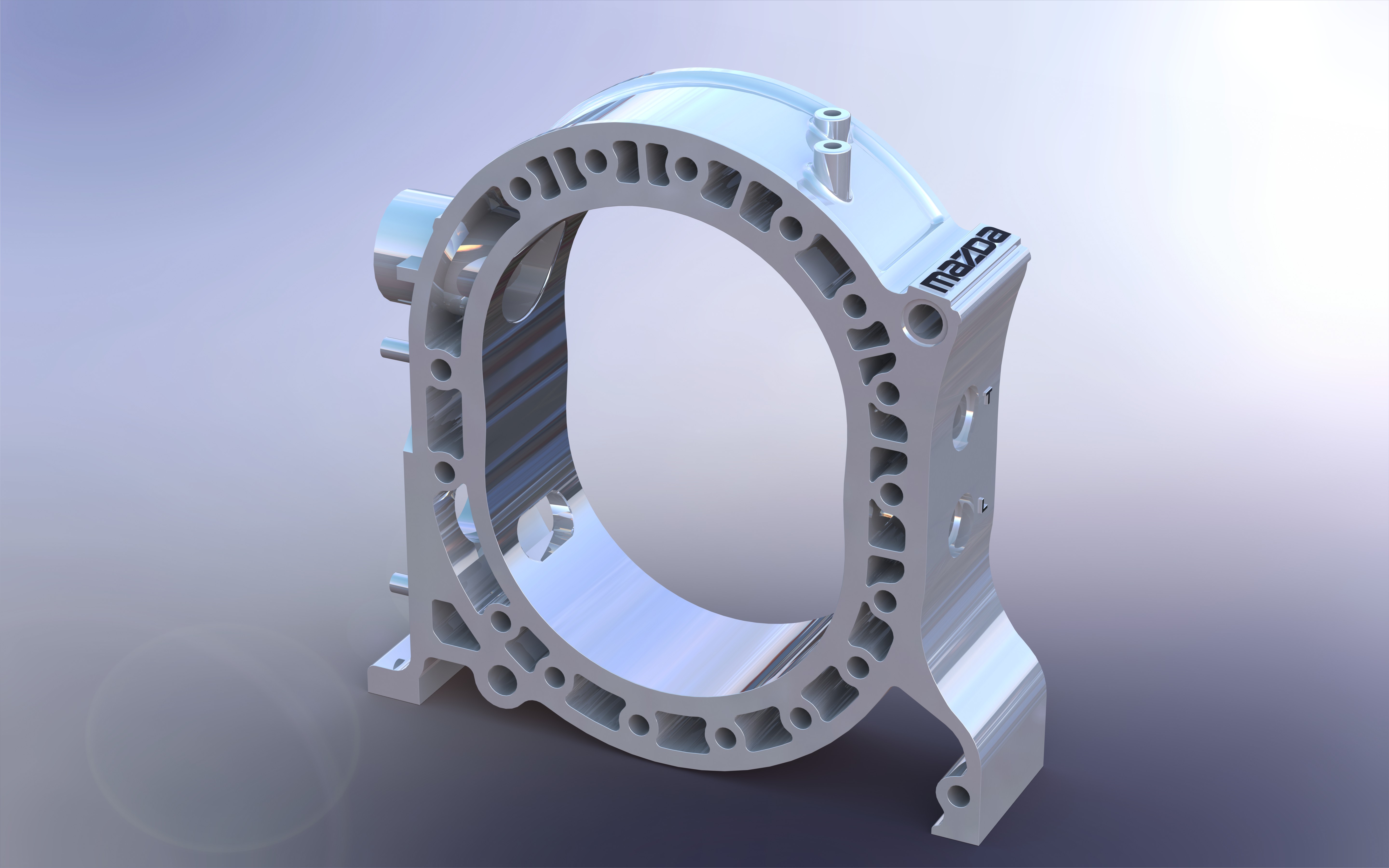
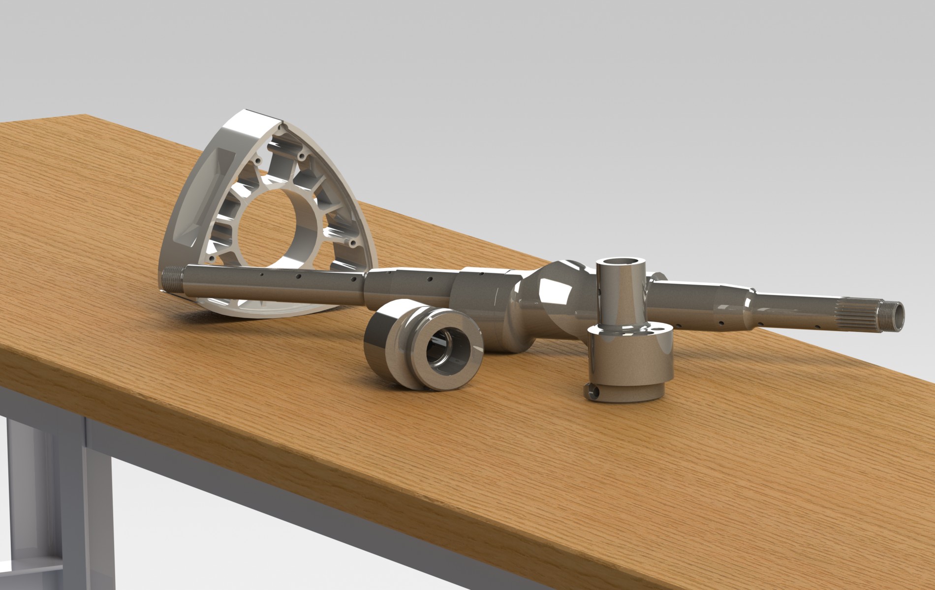
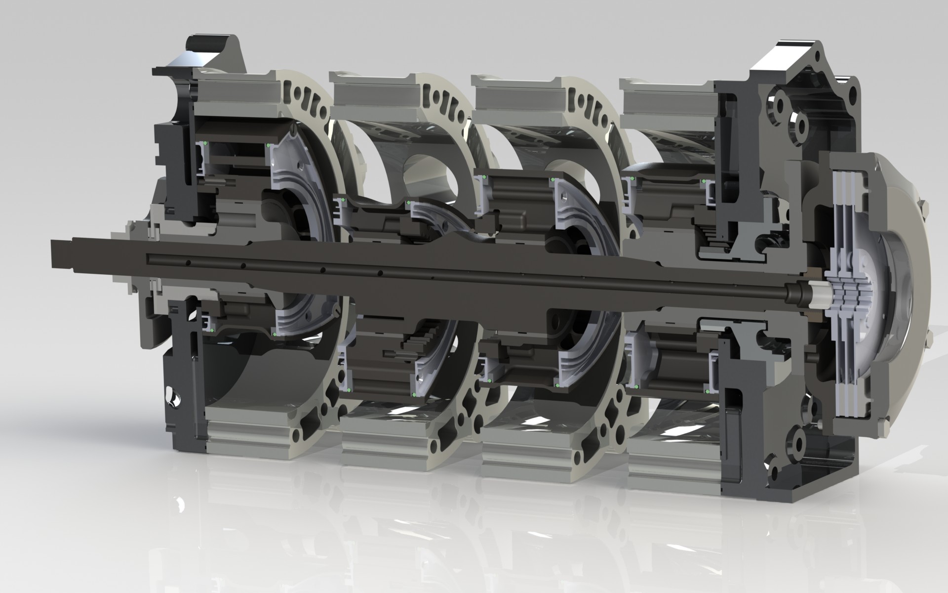
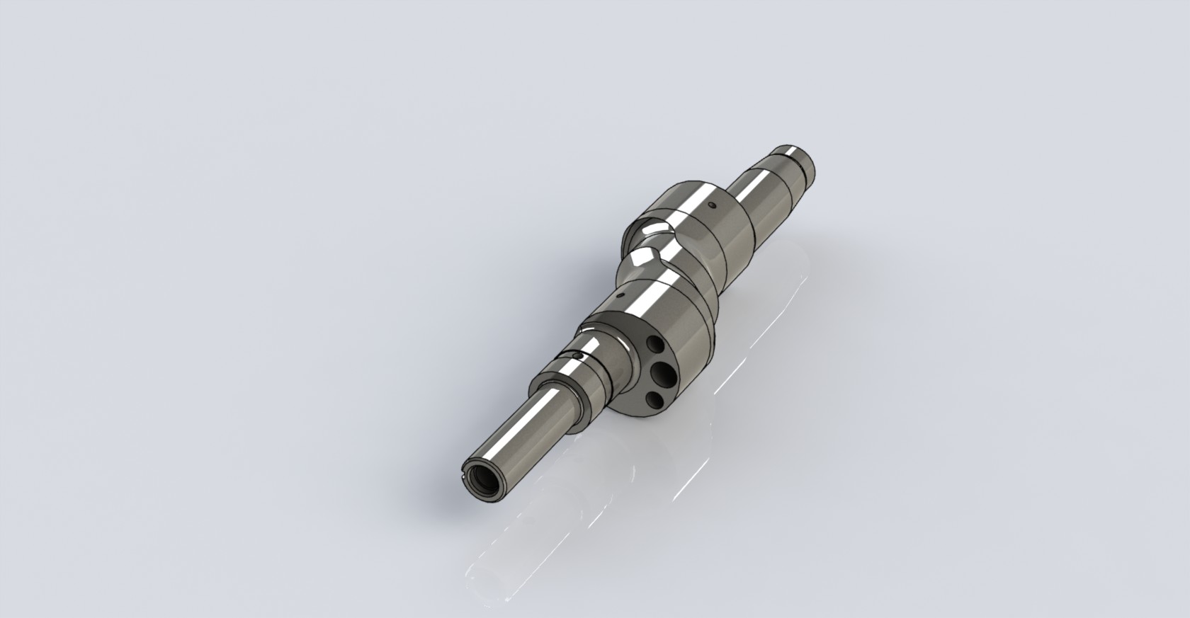
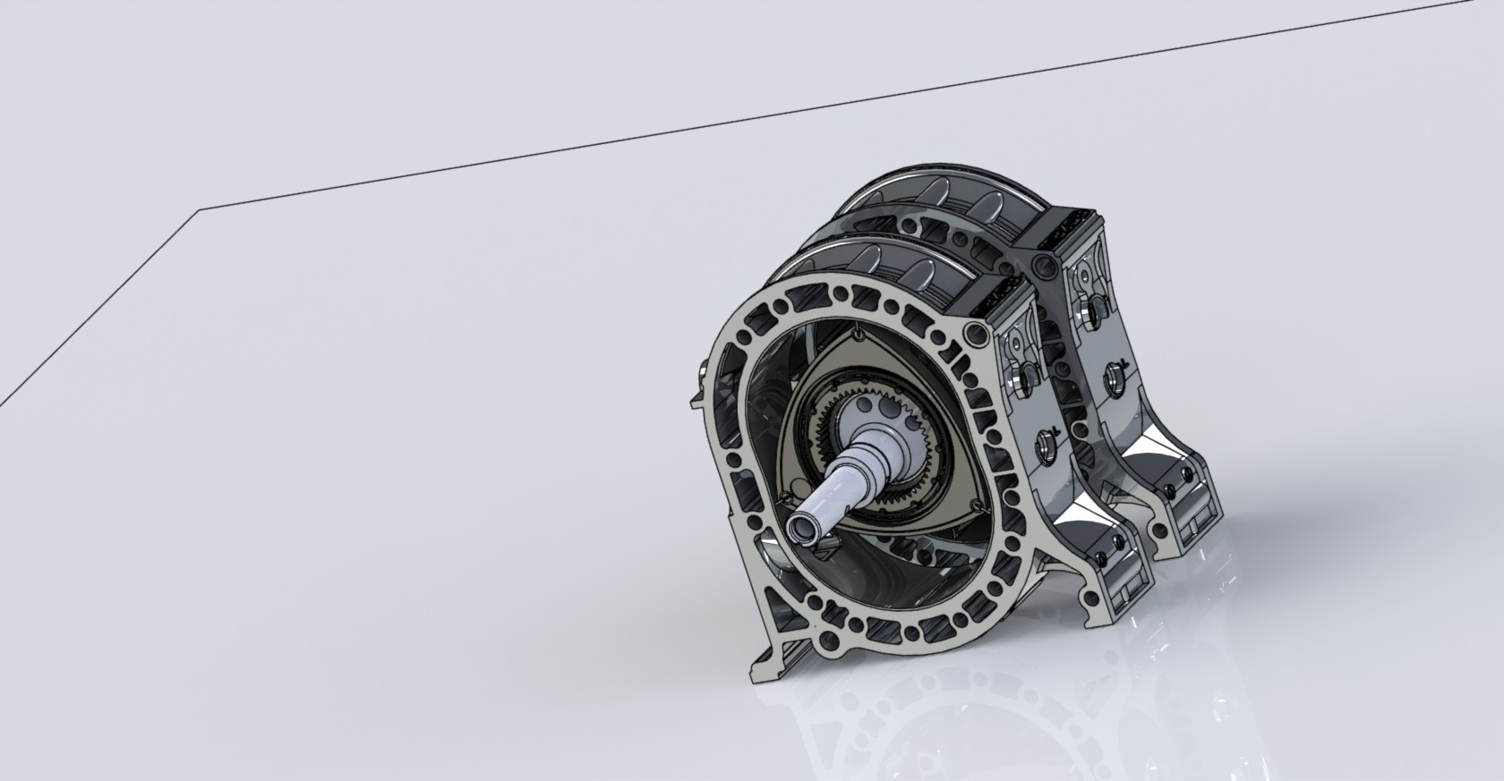
13b-rew CAD/technical drawings
#1
13b-rew CAD/technical drawings
Hi everyone,
So I searched long and hard before starting this project but if these already exist please stop me now.
I have a few ideas floating around in my head for some parts I want to make, mainly to get more experience in the design and manufacturing process and also to put some of the bullshit I learned in school to use. Its awefully hard to design a part meant to bolt up to the engine without a model to design off of so I figured I would model the front cover, waterpump, and everything else on the outside of the engine. Unfortunately those are also a bitch to model.
I am not sure if I will ever post ( or even finish) the entire engine model but for now Ill post what I have and if anyone needs a solidworks file they can PM me. I am no expert on modeling complex things, but with that being said I got all measurements as close as I could. Things like coolant passages, the hollow section of the rotor, or even the rotor reliefs I have no clue how to model and just guessed.
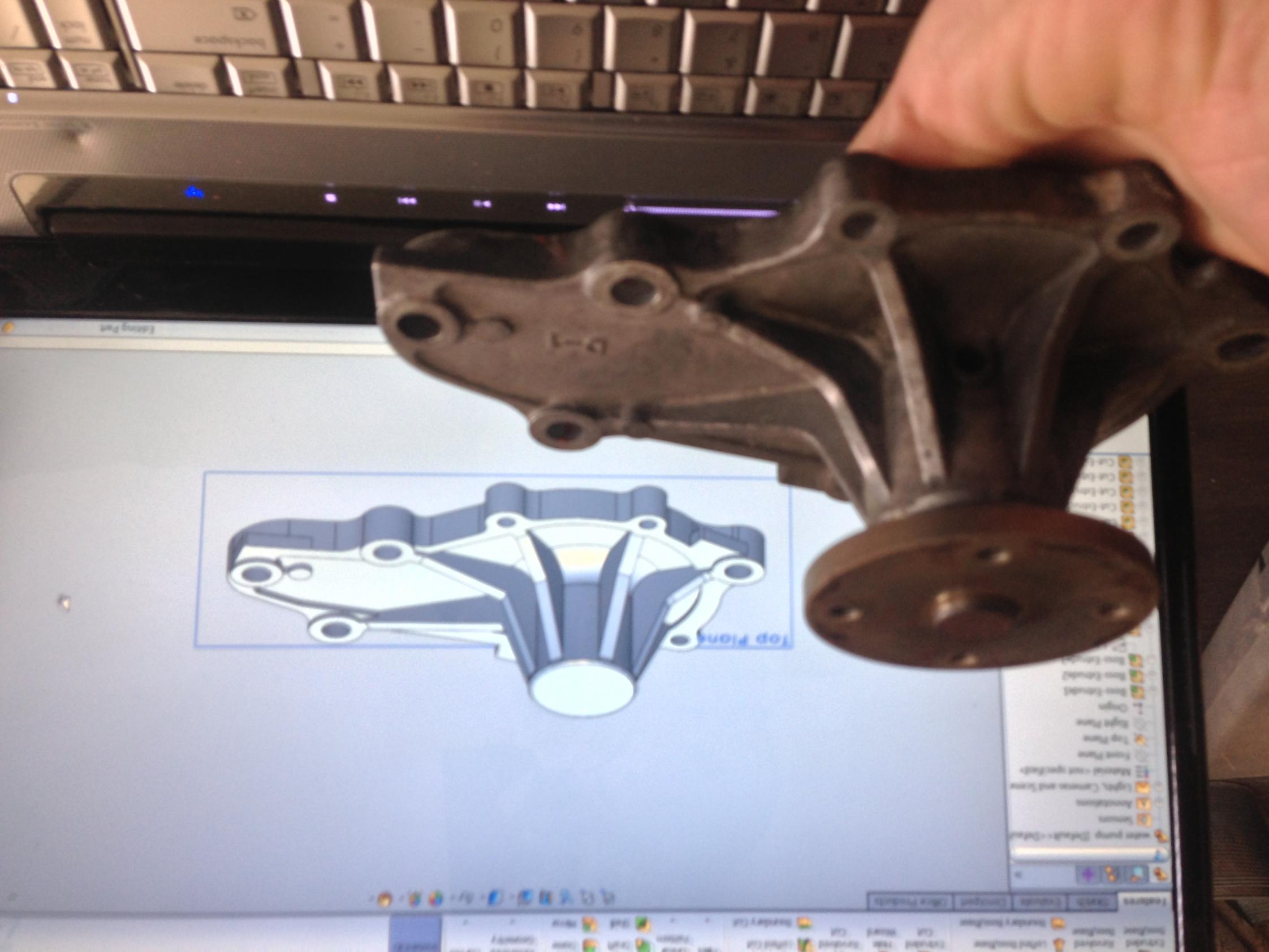
So far I have modeled the water pump and a rotor, I will update the thread when I make progress.


#3
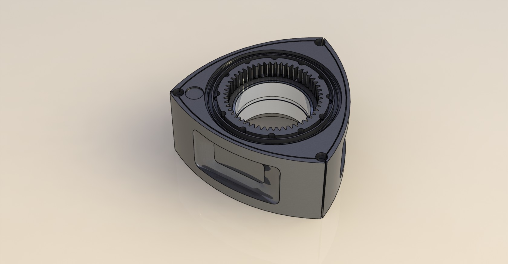
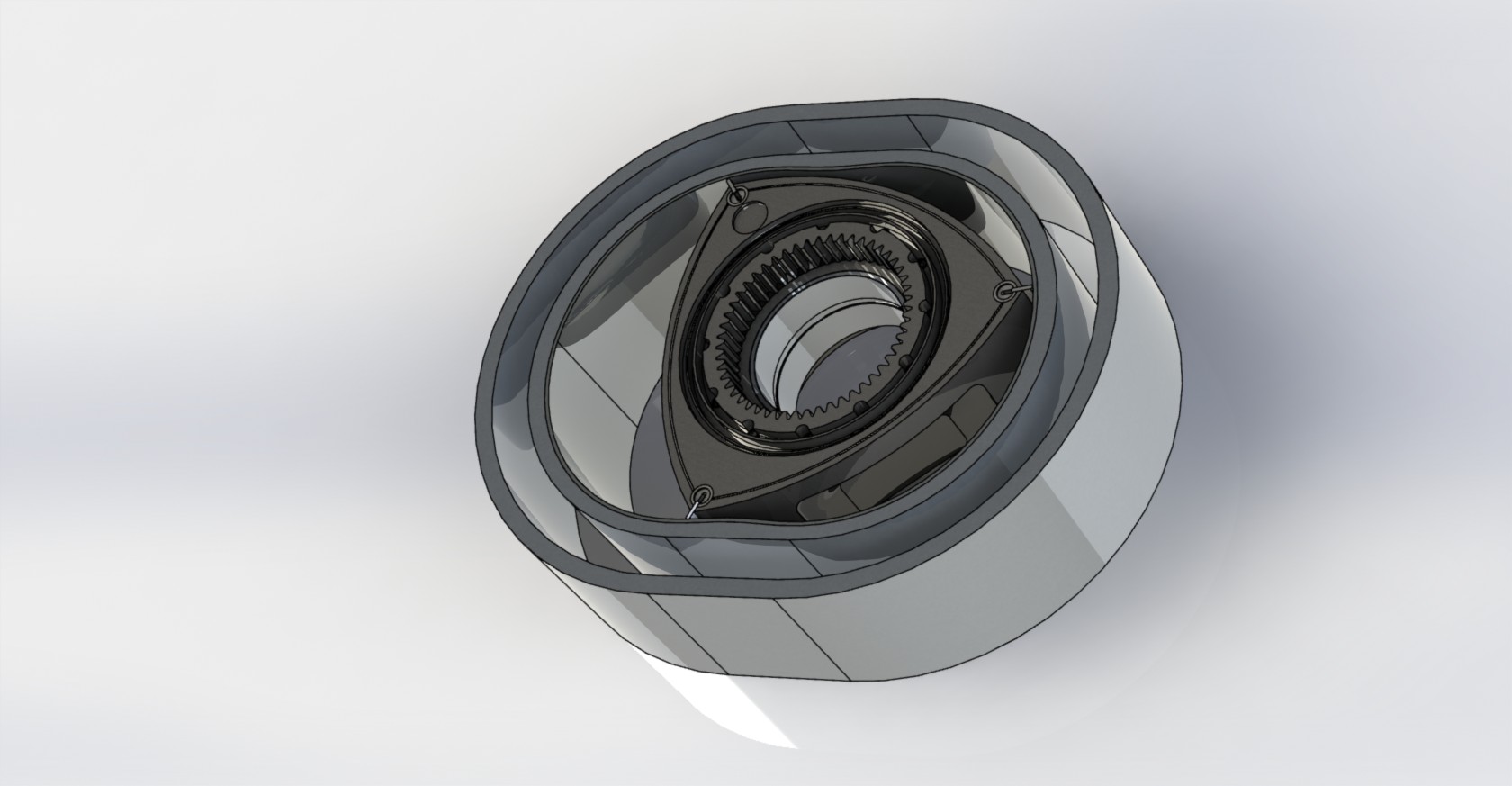
I've modeled a single rotor in Inventor. It is just a representation, but the rotor and epitrochoid housing geometry are all correct and it could be scaled up. The movement is also constrained properly as well and you can drag the rotor through the cycle. Render attached.
If you're interested I can email you a PDF containing formulas for defining the housing and rotor shapes as well as other data that I needed to construct the model.
#5
Thanks! It is a lot of work but I have wanted to make a model for a long time, I modeled the waterpump almost 3 years ago and have done a little bit here and there.
Thanks, I am not quite sure but I am leaning towards making the models publicly available.
Your model looks good, I will send you a PM about the formulas, thanks!!
I have downloaded this model before but it was not detailed enough for what I need. Ill have to check it out again though I may be able to use it for measurements or something.
Originally Posted by alexdimen
Nice work. Do you intend to upload these to a dropbox or something for public access? Start some kind of repository for this information?
I've modeled a single rotor in Inventor. It is just a representation, but the rotor and epitrochoid housing geometry are all correct and it could be scaled up. The movement is also constrained properly as well and you can drag the rotor through the cycle. Render attached.
If you're interested I can email you a PDF containing formulas for defining the housing and rotor shapes as well as other data that I needed to construct the model.
Your model looks good, I will send you a PM about the formulas, thanks!!
Originally Posted by TRRAPLN
Check out GRABCAD.com.
There is a complete rotary engine on there that I used and for this;
There is a complete rotary engine on there that I used and for this;
#6
Started on the rotor housing yesterday, AlexDimen was nice enough to send me a PDF with some equations.
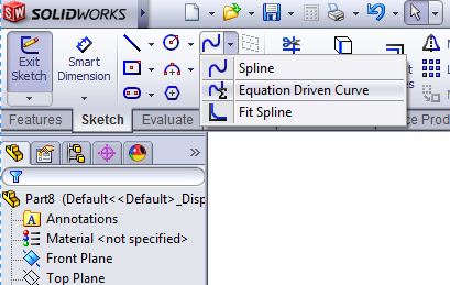
If anyone is curious on how to make the epitrochoid, the easiest method I have found is using the equation driven curve tool in solidworks.
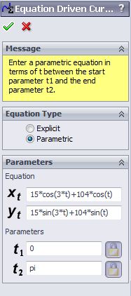
Then enter the set of parametric equations:
X=E*cos(3t)+R*cos(t)
Y=E*sin(3t)+R*sin(t)
Where E is eccentricity, and R is radius of rotor from center to tip. t ranges from 0 to pi, this results in half the epitrochoid and you have to mirror it. I kept getting errors trying to plot the full shape. If you use 15mm and 104mm forE and R make sure solidworks units are set to metric.


If anyone is curious on how to make the epitrochoid, the easiest method I have found is using the equation driven curve tool in solidworks.

Then enter the set of parametric equations:
X=E*cos(3t)+R*cos(t)
Y=E*sin(3t)+R*sin(t)
Where E is eccentricity, and R is radius of rotor from center to tip. t ranges from 0 to pi, this results in half the epitrochoid and you have to mirror it. I kept getting errors trying to plot the full shape. If you use 15mm and 104mm forE and R make sure solidworks units are set to metric.


Trending Topics
#8
To make the stuff with contours (cast parts) you'll need to work with surface features. That gets really labor intensive.
Good luck, it will take a lot of time but the result could be pretty cool.
David
Good luck, it will take a lot of time but the result could be pretty cool.
David
#9
This makes me wonder things like:
Does anyone, including Mazda, have any published detail drawings on any of these engine parts? Kind of like that outfit that built the 12 rotor engine. If I remember right, they machined Al irons, Al housings, and iron faces out of steel.
Also, I think things like upgraded rotor housings (to aid coolant surface area, etc.) could be designed in CAD (If they haven't already).
Finally, if one had a laser 3-D scanner, one could scan things like rotors, clean them up in CAD, and they could reproduced.
#10
I can tell you right now that the people who designed these parts are dead or mostly retired now. I mean we're talking about 1987 or so when this engine was designed, as a variant of it launched in the Cosmo before the FD. And they did almost all of it by hand with actual paper and drafting boards. The drawings are probably long gone, or if they're still around they are on something prehistoric like some microfilm in a box somewhere.
#11
Originally Posted by dgeesaman
To make the stuff with contours (cast parts) you'll need to work with surface features. That gets really labor intensive.
Good luck, it will take a lot of time but the result could be pretty cool.
David
Good luck, it will take a lot of time but the result could be pretty cool.
David
Originally Posted by quichedem
This makes me wonder things like:
Does anyone, including Mazda, have any published detail drawings on any of these engine parts? Kind of like that outfit that built the 12 rotor engine. If I remember right, they machined Al irons, Al housings, and iron faces out of steel.
Also, I think things like upgraded rotor housings (to aid coolant surface area, etc.) could be designed in CAD (If they haven't already).
Finally, if one had a laser 3-D scanner, one could scan things like rotors, clean them up in CAD, and they could reproduced.
Does anyone, including Mazda, have any published detail drawings on any of these engine parts? Kind of like that outfit that built the 12 rotor engine. If I remember right, they machined Al irons, Al housings, and iron faces out of steel.
Also, I think things like upgraded rotor housings (to aid coolant surface area, etc.) could be designed in CAD (If they haven't already).
Finally, if one had a laser 3-D scanner, one could scan things like rotors, clean them up in CAD, and they could reproduced.
I would love to mess around with a 3-d scanner and see what it can do. or a 3d measuring arm would be awesome for dimensioning all the bolt holes. The university here has a 3d scanner but I couldnt get it to work and of course nobody that works in the building knows how either.
#12
This makes me wonder things like:
Does anyone, including Mazda, have any published detail drawings on any of these engine parts? Kind of like that outfit that built the 12 rotor engine. If I remember right, they machined Al irons, Al housings, and iron faces out of steel.
Also, I think things like upgraded rotor housings (to aid coolant surface area, etc.) could be designed in CAD (If they haven't already).
Finally, if one had a laser 3-D scanner, one could scan things like rotors, clean them up in CAD, and they could reproduced.
Does anyone, including Mazda, have any published detail drawings on any of these engine parts? Kind of like that outfit that built the 12 rotor engine. If I remember right, they machined Al irons, Al housings, and iron faces out of steel.
Also, I think things like upgraded rotor housings (to aid coolant surface area, etc.) could be designed in CAD (If they haven't already).
Finally, if one had a laser 3-D scanner, one could scan things like rotors, clean them up in CAD, and they could reproduced.
A 3D scanner or CMM would certainly help get the forms correct, but it takes immense hours and for what? Pretty pictures?
David
#16
Jesus! 
At the moment I have access to a Zeiss CMM and have some irons (front and middle) at work right now. My friend who is a machinist and I are trying our hands at surface grinding some that I got for free. I could ask for our guy to pull some dimensions if needed.

Thanks!
I have spent a few hours messing with surfaces and it was a pain. I will do as much as I can hopefully I will pick up some new techniques along the way.
Published definitely not. I am sure several people/companies have at least partial solid models but do not want to share.
I would love to mess around with a 3-d scanner and see what it can do. or a 3d measuring arm would be awesome for dimensioning all the bolt holes. The university here has a 3d scanner but I couldnt get it to work and of course nobody that works in the building knows how either.
#17
Was able to work on the housing for a few more hours when I was bored today.
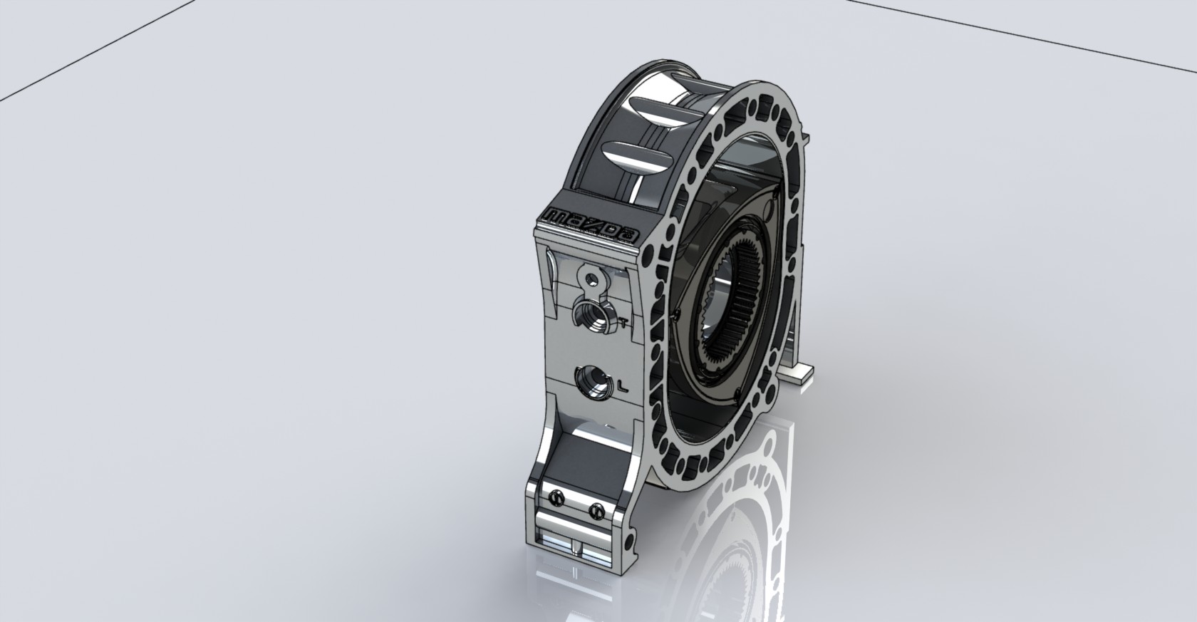
if anyone was wondering, or has a better way.... this is what I did to get to get the bolt hole locations.
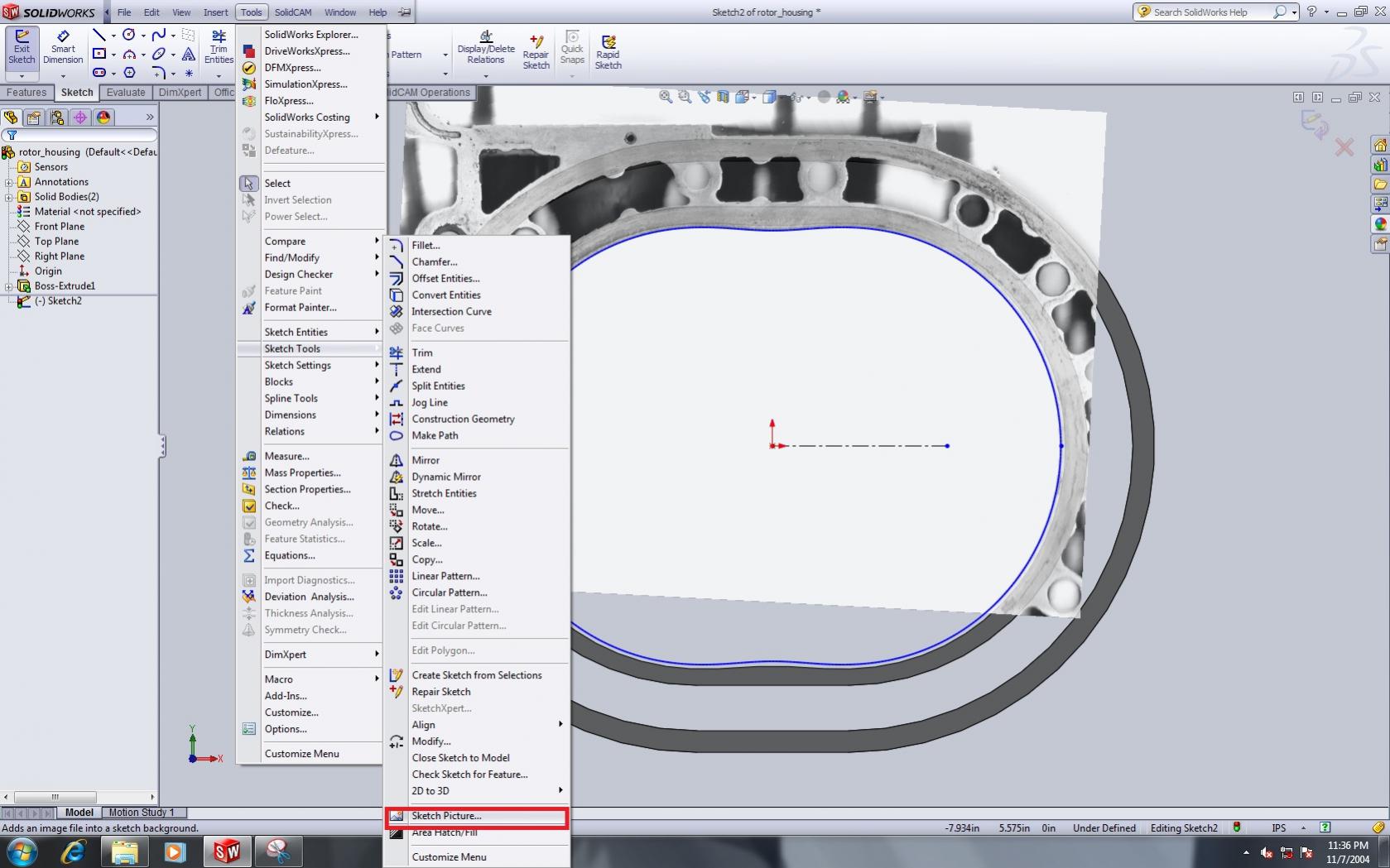
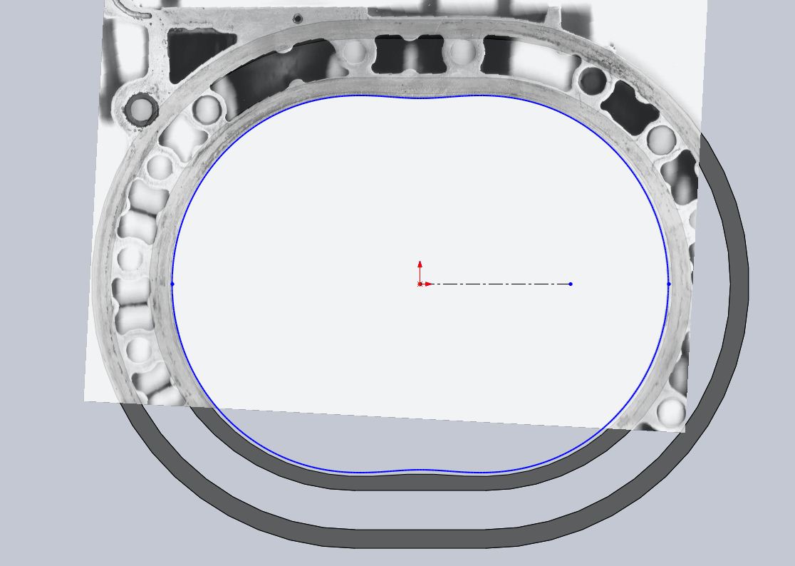

if anyone was wondering, or has a better way.... this is what I did to get to get the bolt hole locations.


#19
Yeah, epic thread is epic!
You still got some catching up to do to the 12-rotor maniacs, though:
12ROTOR IN CAR CONFIRMED! | Performance Garage ? V8, HI-TECH, MUSCLE, IMPORT, HOTROD, EXOTIC, RACE, CUSTOM
Those animals machined everything!!
You still got some catching up to do to the 12-rotor maniacs, though:
12ROTOR IN CAR CONFIRMED! | Performance Garage ? V8, HI-TECH, MUSCLE, IMPORT, HOTROD, EXOTIC, RACE, CUSTOM
Those animals machined everything!!
#20
Havent modeled anything else on the engine but I did find a render of the completed waterpump I modeled a while ago. Maybe someday I will finish the front iron and water pump housing so I can put this to use.
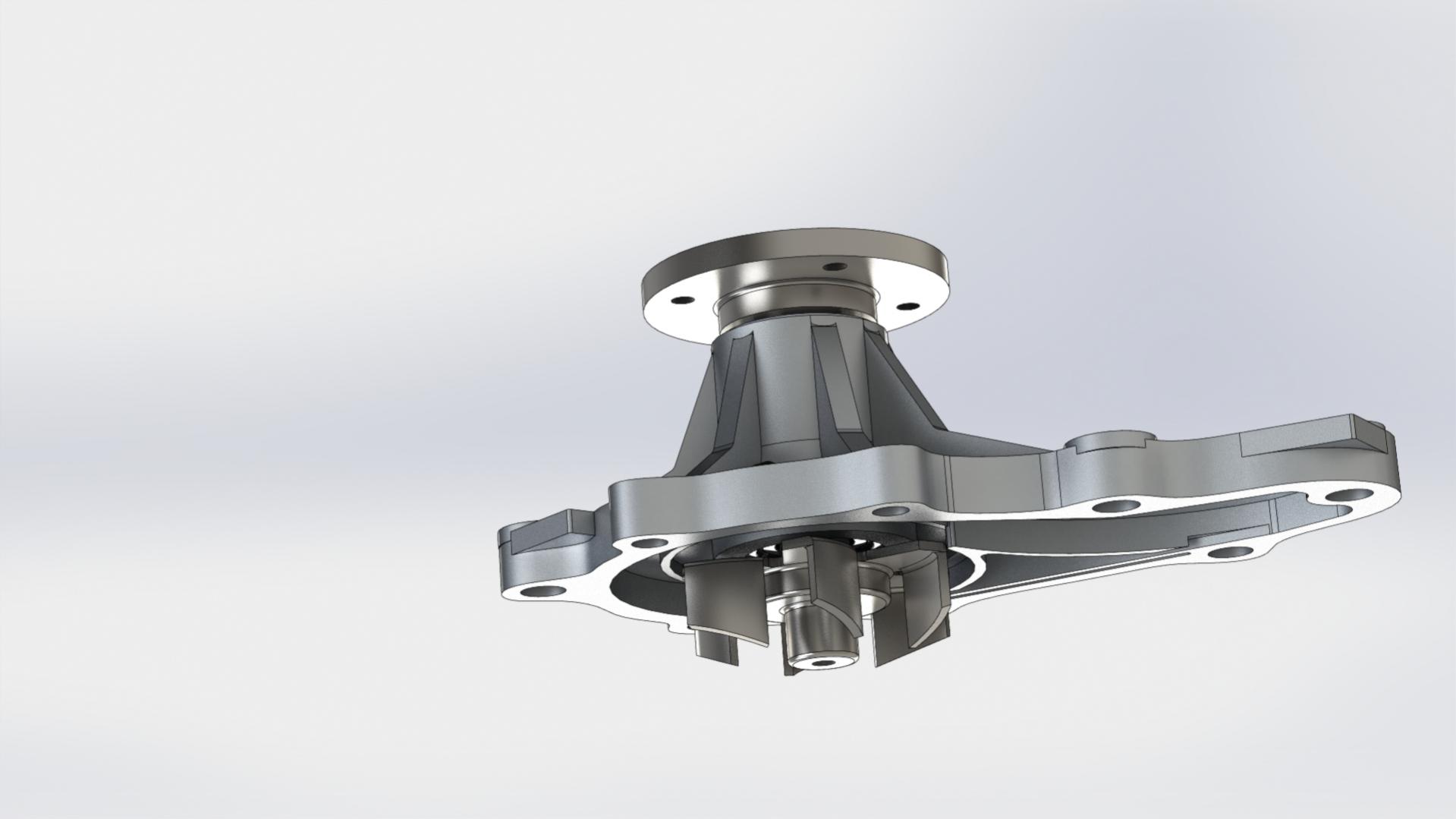

#21
#24
I do mechanical design for large hydropower turbines at work here, using AutoCad packages as well.
I have so much work, I get home and don't even want to look at a computer, let alone model much of anything else. I did a model of my Holden (Chevrolet) Caprice at home the other day and I wasn't feeling it. I don't think I'll be putting in the extra curricular work like these guys any time soon!!
I have so much work, I get home and don't even want to look at a computer, let alone model much of anything else. I did a model of my Holden (Chevrolet) Caprice at home the other day and I wasn't feeling it. I don't think I'll be putting in the extra curricular work like these guys any time soon!!
#25
I do mechanical design for large hydropower turbines at work here, using AutoCad packages as well.
I have so much work, I get home and don't even want to look at a computer, let alone model much of anything else. I did a model of my Holden (Chevrolet) Caprice at home the other day and I wasn't feeling it. I don't think I'll be putting in the extra curricular work like these guys any time soon!!
I have so much work, I get home and don't even want to look at a computer, let alone model much of anything else. I did a model of my Holden (Chevrolet) Caprice at home the other day and I wasn't feeling it. I don't think I'll be putting in the extra curricular work like these guys any time soon!!
Small update, did some work on the center iron.
