WRITE-UP: Error Reporting Lights in Center Console
 04-24-07, 03:20 PM
#1
s4 Tails for Life!
Thread Starter
Join Date: Feb 2005
Location: Dallas, TX
Posts: 577
Likes: 0
Received 0 Likes
on
0 Posts
Hey everyone,
So I was asking earlier about our cars and On-Board Diagnostics. (LINKAGE! ) Turns out we don't have too much in the way of error reporting / scanning / OBD.
Taken from this webpage (all credit due them, not me): http://www.teamfc3s.org/info/article...odes/main.html
These are the LEDs I used: (the ones recommended on the teamfc3s site.)
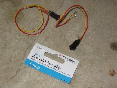
You will also need male quick disconnect ends. (Radioshack part no. 64-3134)
The LEDs are radioshack part no. 276-011
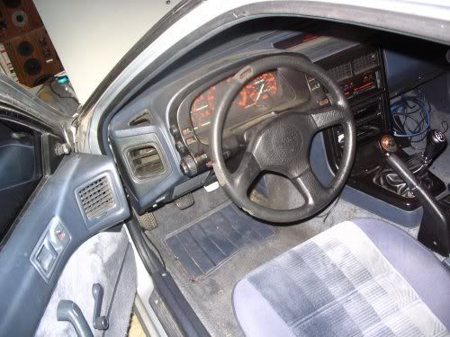
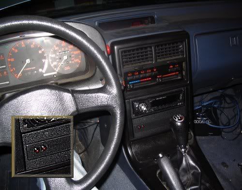
Now choose where you want them to be placed in your car. I chose the blank plate below my after-market radio.
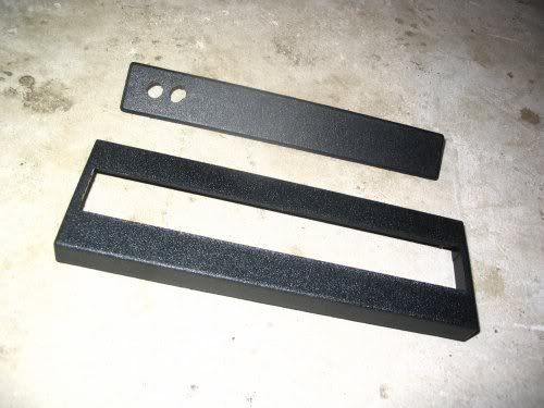
If you want to do this, just drill two holes in the plate. (Make sure you don't drill too large! You can always drill out more but you can't put any back!!)
Run the LEDs through:
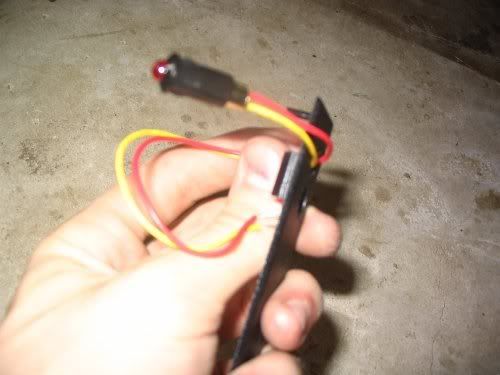
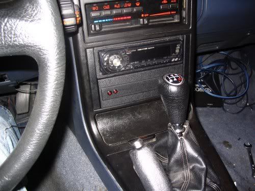
And make sure they fit snuggly in place:
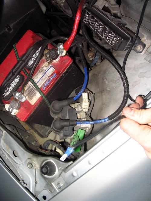
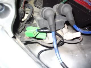
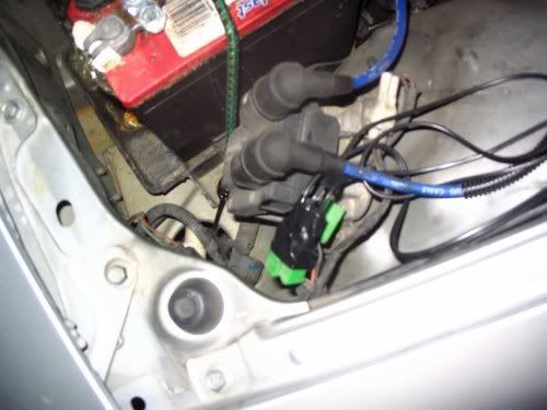
OK, now, where are we getting these error codes? RIght here:
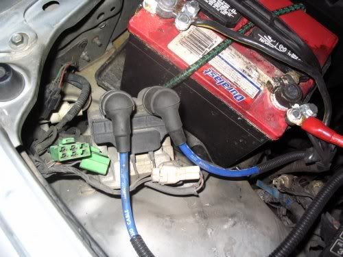
It's the green six pin connector on the left, fyi.
Using the instructions on teamfc3s we are going to run three wires from that green connector to the center console.
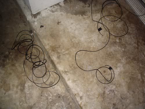
First, we don't have enough wire to get from the engine bay to the interior. I used regular speaker wire to extend the LEDs existing wires. It should work just fine.
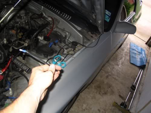
Run some speaker wire from the engine bay to the interior. I went through the driver's door hinge area. There may be a better way, that's just how I did it.
Make sure you have enough wire!!!
We will (for all practical purposes) be running three wires. You'll need "one" length of speaker wire (with the two ends - what would normally be left and right channel) and then two separate wires (separate another length of speaker wire, so they are literally one wire each.)
I put electrical tape on both ends of the DCC1 wire so I could tell it apart from the DCC2 wire. (And of course, the ABR wire should be obvious with two end.)
If you're confused, visit teamfc3s. I linked it above.
The wire with two ends goes to the ABR. The individual wires go to DCC1 and DCC2 on the diagnostic connector.
Here's a diagram from the teamfc3s site. (I didn't ask permission to use this image, I will remove it if necessary but of course I'm giving all credit to them and not myself.)

You'll run wires out of those connections and into your LEDs, like so:
Run your wires and strip the engine bay ends. Add the quick disconnect connectors on the end (example
And plug them in!
Now use electrical tape to hold it all in place:
And let's move to the interior!
I disconnected the negative battery cable just because electricity scares the pants off of me, I'm not sure if it's necessary or not.
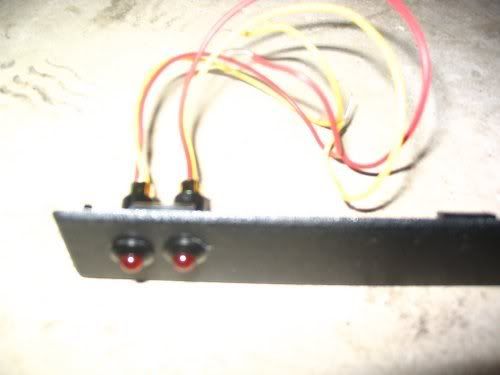
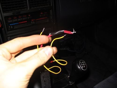
Now, the ABR wire (with two ends) goes to both the red wires on the two LEDs. The yellow wires connect to DCC1 and DCC2. It is, of course, your choice how to set them up. I chose DCC1 to be closest to the driver and DCC2 to be farther away. (Since we read left to right this system made the most sense to me.)
Once everything is connected, you're done!
Admire!
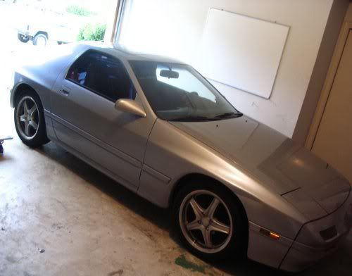
And now to show off my baby:
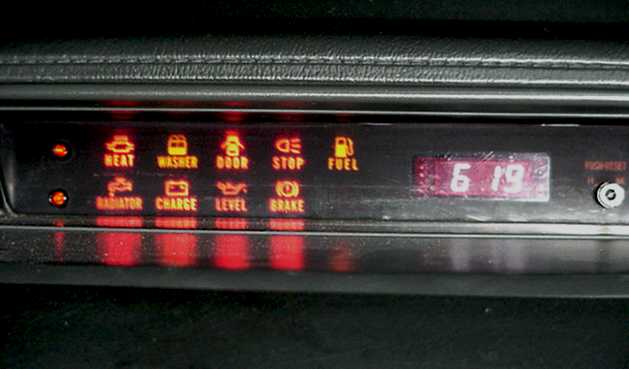
OK, are you ready to test them out? If you hooked everything up right the LEDs will light up with the idiot cluster lights and go out along with them after startup. (Assuming you don't have any error codes being displayed.)
Check it out: (a short video) http://www.youtube.com/watch?v=w-pH3GULE5s
Enjoy!
Cheers,
Cody
I guess I didn't even really say what these do, eh? Well it explains it in greater detail on the teamfc3s site but they report error codes by flashing in different patterns / lengths.
Here's the list of error codes from teamfc3s:
So I was asking earlier about our cars and On-Board Diagnostics. (LINKAGE! ) Turns out we don't have too much in the way of error reporting / scanning / OBD.
Taken from this webpage (all credit due them, not me): http://www.teamfc3s.org/info/article...odes/main.html
These are the LEDs I used: (the ones recommended on the teamfc3s site.)
You will also need male quick disconnect ends. (Radioshack part no. 64-3134)
The LEDs are radioshack part no. 276-011
Now choose where you want them to be placed in your car. I chose the blank plate below my after-market radio.
If you want to do this, just drill two holes in the plate. (Make sure you don't drill too large! You can always drill out more but you can't put any back!!)
Run the LEDs through:
And make sure they fit snuggly in place:
OK, now, where are we getting these error codes? RIght here:
It's the green six pin connector on the left, fyi.
Using the instructions on teamfc3s we are going to run three wires from that green connector to the center console.
First, we don't have enough wire to get from the engine bay to the interior. I used regular speaker wire to extend the LEDs existing wires. It should work just fine.
Run some speaker wire from the engine bay to the interior. I went through the driver's door hinge area. There may be a better way, that's just how I did it.
Make sure you have enough wire!!!
We will (for all practical purposes) be running three wires. You'll need "one" length of speaker wire (with the two ends - what would normally be left and right channel) and then two separate wires (separate another length of speaker wire, so they are literally one wire each.)
I put electrical tape on both ends of the DCC1 wire so I could tell it apart from the DCC2 wire. (And of course, the ABR wire should be obvious with two end.)
If you're confused, visit teamfc3s. I linked it above.
The wire with two ends goes to the ABR. The individual wires go to DCC1 and DCC2 on the diagnostic connector.
Here's a diagram from the teamfc3s site. (I didn't ask permission to use this image, I will remove it if necessary but of course I'm giving all credit to them and not myself.)
You'll run wires out of those connections and into your LEDs, like so:
Run your wires and strip the engine bay ends. Add the quick disconnect connectors on the end (example
And plug them in!
Now use electrical tape to hold it all in place:
And let's move to the interior!
I disconnected the negative battery cable just because electricity scares the pants off of me, I'm not sure if it's necessary or not.
Now, the ABR wire (with two ends) goes to both the red wires on the two LEDs. The yellow wires connect to DCC1 and DCC2. It is, of course, your choice how to set them up. I chose DCC1 to be closest to the driver and DCC2 to be farther away. (Since we read left to right this system made the most sense to me.)
Once everything is connected, you're done!
Admire!
And now to show off my baby:
OK, are you ready to test them out? If you hooked everything up right the LEDs will light up with the idiot cluster lights and go out along with them after startup. (Assuming you don't have any error codes being displayed.)
Check it out: (a short video) http://www.youtube.com/watch?v=w-pH3GULE5s
Enjoy!
Cheers,
Cody
I guess I didn't even really say what these do, eh? Well it explains it in greater detail on the teamfc3s site but they report error codes by flashing in different patterns / lengths.
Here's the list of error codes from teamfc3s:
With the LED tester monitoring DCC1 and DCC2, turn the key switch to ON. The two LED's will go on for about 3 seconds and then will go off. If there are no more LED flashes, this indicates that there are no immediate failures.
The codes are displayed with a sort of Morse code. There are short (1/2 second) flashes of light which correspond to a count of 1 and long (2 seconds) flashes which correspond to a 5. These pulses are counted until the long pause (2 seconds) that indicates the end of the code.
DCC1 indicates the one's digit of the error code and DCC2 indicates the ten's digit. DCC1 will flash either short or long pulses. Because of the limited number of two-digit codes (12 and 15) DCC2 will only indicate a short pulse which counts as 10. There is a long pause after which time the code will be redisplayed.
A code displayed doesn't necessarily mean that the sensor described is faulty. It could also be caused by a bad connector, loose wiring or a defective ECU. The possible error codes are summarizes in the list below. 'S' indicates a short pulse (about 1/2 sec), 'L' indicates a long pulse (about 1 sec), 'P' indicates the pause (about 2 sec) between the cycles, and '...' indicates repetition.
Code 01 - Crank angle sensor
DCC1: S P .... (1 short light... long pause ... repeat),
DCC2: does not light.
Fail-safe mode: There is no fail-safe mode for this sensor.
Code 02 - Air flow meter.
DCC1: SS P ... (2 short lights... long pause ... repeat)
DCC2: does not light
Fail-safe mode: Maintains basic signal at preset level.
Code 03 - Water thermo sensor.
DCC1: SSS P .... (3 short lights... long pause ... repeat)
DCC2: does not light
Fail-safe mode: Maintains a constant 80 degree C command.
Comments: this is the two-wire sensor on the back of the thermostat housing
Code 04 - Intake air temp sensor.
DCC1: SSSS P .... (4 short lights... long pause ... repeat)
DCC2: does not light
Fail-safe mode: Maintains constant 20 degree C command.
Comments: This sensor is built into the air flow meter.
Code 05 - Oxygen (O2) sensor.
DCC1: L P.... (1 long light... long pause ... repeat)
DCC2: does not light
Fail-safe mode: The ECU stops feedback correction (open loop operation)
Comments: This sensor is located on the down-pipe / pre-cat.
Code 06 - Throttle sensor.
DCC1: LS P ... (1 long light ... 1 short light ... long pause ... repeat)
DCC2: does not light
Fail-safe mode: The ECU assumes 100% throttle position.
Comments: This is the TPS and it is located underneath the intercooler.
Code 07 - Boost/Pressure sensor.
DCC1: LSS P ... (1 long light ... 2 short lights ... long pause ... repeat)
DCC2: does not light
Fail-safe mode: Maintains constant command: 96 mm Hg (boost sensor), 26.3 kPa (pressure sensor)
Comments: This is located on the right shock tower.
Code 09 - Atmospheric Pressure sensor.
DCC1: LSSSS P ... (1 long light ... 4 short lights ... long pause ... repeat)
DCC2: does not light
Fail-safe mode: Maintains constant sea-level command (boost sensor)
Comments: This is located next to the ECU.
Code 12 - Trailing side coil failure.
DCC1: SS P ... (2 short lights ... long pause ... repeat)
DCC2: S P ... (1 short light ... long pause ... repeat)
Fail-safe mode: Stops operation of trailing side ignition
Comments: indicates a failure within the trailing side ignition system.
Code 15 - Intake air temperature sensor.
DCC1: L P ... (1 long light ... long pause ... repeat)
DCC2: S P ... (1 short light ... long pause ... repeat)
Fail-safe mode: Maintains constant 20C (68F) command.
Comments: This is located on the intake air pipe just prior to the throttle body.
Note: From our observations, it seems that if more than one error code exists, the ECU reports only the one of lower numeric value. If you have any information that support/refute this assumption please let us know so we can update the document.
Last edited by iSP33D-for-J3SUS; 04-24-07 at 03:25 PM.
 04-24-07, 05:56 PM
#2
Technician
iTrader: (1)
Join Date: Aug 2006
Location: Virginia
Posts: 1,008
Likes: 0
Received 0 Likes
on
0 Posts
interesting. Thanks for the write up. Quick question though; how did you run the wire? Did you follow the engine harness somewhere or did you drill and tap a new hole and bunge in the fire wall?
 04-24-07, 06:53 PM
#4
Technician
iTrader: (1)
Join Date: Aug 2006
Location: Virginia
Posts: 1,008
Likes: 0
Received 0 Likes
on
0 Posts
Originally Posted by stevensimon
all you have to do is read it... he said he ran it through the door jamb
 04-24-07, 09:09 PM
#7
Full Member

Join Date: Apr 2007
Location: raleigh
Posts: 127
Likes: 0
Received 0 Likes
on
0 Posts
Originally Posted by highwayinthesky
if you cant put 3 wires into the engine bay what are you going to do when you get an error code?

Trending Topics
04-24-07, 09:44 PM
#8
Full Member
Join Date: May 2006
Location: calgary
Posts: 225
Likes: 0
Received 0 Likes
on
0 Posts
by the way thanks isp33d for the great write up and pics, i think one day this might save someones motor or at least a lot of trouble shooting time.
is there a weather pack connector that with plug into the 6 pin connector? this would give a more stock looking mod and also allow for a real diagnostic tool to still be used without having to mess with your mod.
is there a weather pack connector that with plug into the 6 pin connector? this would give a more stock looking mod and also allow for a real diagnostic tool to still be used without having to mess with your mod.
04-24-07, 09:49 PM
#9
Strength and Honor
Join Date: Apr 2006
Location: CA bay area
Posts: 391
Likes: 0
Received 0 Likes
on
0 Posts
You can also put the LEDs in the accessory slot near the emergency brake, per this write-up:
http://howto.globalvicinity.com/gv_w...i=39&co=1&vi=1
Check it for the S5 version too.
http://howto.globalvicinity.com/gv_w...i=39&co=1&vi=1
Check it for the S5 version too.
04-24-07, 10:40 PM
#11
s4 Tails for Life!
Thread Starter
Join Date: Feb 2005
Location: Dallas, TX
Posts: 577
Likes: 0
Received 0 Likes
on
0 Posts
Originally Posted by lax-rotor
interesting. Thanks for the write up. Quick question though; how did you run the wire? Did you follow the engine harness somewhere or did you drill and tap a new hole and bunge in the fire wall?
I'll see how well this works. I'd like to hide it even better, perhaps. But, hey, it works!
Cheers,
Cody
04-24-07, 11:06 PM
#12
Strength and Honor
Join Date: Apr 2006
Location: CA bay area
Posts: 391
Likes: 0
Received 0 Likes
on
0 Posts
The way I did it is through one of the rubber firewall grommets, then to the center console (you could stop there), under the carpet, and into the accessory port near the emergency brake.
04-24-07, 11:20 PM
#13
Long rifle.
iTrader: (1)
Join Date: Aug 2006
Location: pittsburgh
Posts: 653
Likes: 0
Received 0 Likes
on
0 Posts
Great writeup and pics. I would suggest finding another way to route the wires from the engine bay to the interior. Through the door jam is a surefire way to pinch off the wires and 1. blow fuses, 2 damage something, or 3 start a fire if not fused off.
The left hand harness is right there at the upper part of the firewall beside your clutch maste cylinder, you could run it through that, or through the hole for the ABS harness.
The left hand harness is right there at the upper part of the firewall beside your clutch maste cylinder, you could run it through that, or through the hole for the ABS harness.
04-25-07, 12:25 AM
#14
I'm a boost creep...
Join Date: Jan 2002
Location: Auckland, New Zealand
Posts: 15,608
Likes: 0
Received 8 Likes
on
8 Posts
Good write-up, but I'm way ahead of you. About four years ahead in fact... 
The LED's look dim in that photo, but the're actually off. The light's just from the flash. When they're on they're not easily missed.
Using the same holes the factory used for wiring is better. Poke a small hole on the rubber boot and fed the wires through. I avoided this entirely be connecting my LED's at the ECU instead of the engine bay plug. 
You'll have noticed by now that the O2 sensor code flashes until the sensor heats up...
The LED's look dim in that photo, but the're actually off. The light's just from the flash. When they're on they're not easily missed.
Originally Posted by iSP33D-for-J3SUS
Run some speaker wire from the engine bay to the interior. I went through the driver's door hinge area. There may be a better way, that's just how I did it.
You'll have noticed by now that the O2 sensor code flashes until the sensor heats up...
04-25-07, 12:36 AM
#15
Strength and Honor
Join Date: Apr 2006
Location: CA bay area
Posts: 391
Likes: 0
Received 0 Likes
on
0 Posts
Originally Posted by NZConvertible
Good write-up, but I'm way ahead of you. About four years ahead in fact...
The LED's look dim in that photo, but the're actually off. The light's just from the flash. When they're on they're not easily missed.
Using the same holes the factory used for wiring is better. Poke a small hole on the rubber boot and fed the wires through. I avoided this entirely be connecting my LED's at the ECU instead of the engine bay plug.
You'll have noticed by now that the O2 sensor code flashes until the sensor heats up...
edit: PM
Last edited by stevej88na; 04-25-07 at 12:42 AM.
04-25-07, 07:48 AM
#18
I'm a boost creep...
Join Date: Jan 2002
Location: Auckland, New Zealand
Posts: 15,608
Likes: 0
Received 8 Likes
on
8 Posts
On my vert there was two empty spaces at the left end where the HATCH and COOLING FAN warning lights go. I just drilled holes in the face plate to mount the LED's similar to as described above. No photos sorry, I did this four years ago when I didn't even own a digital camera.
04-25-07, 01:21 PM
#21
Rotary Freak

Join Date: Dec 2006
Location: New Hampshire
Posts: 1,791
Likes: 0
Received 0 Likes
on
0 Posts
That's the best placement/technique I've seen so far.
I found them annoying. If my engine acts up, there is only a couple sensors now that could be the calprit and usually its takes 2 seconds to find out and fix it.If you notice that the LEDs flash VERY quickly at times, thats the ECU telling you what the AFR is
04-26-07, 12:32 AM
#22
I'm a boost creep...
Join Date: Jan 2002
Location: Auckland, New Zealand
Posts: 15,608
Likes: 0
Received 8 Likes
on
8 Posts
Originally Posted by My5ABaby
I have one empty slot over there, but you don't think the Hatch light is nice to keep?
Originally Posted by RotaMan99
I find the LEDs not very helpfull at all. They usually blink telling me something is wrong when there really isn't. Maybe thats because I have removed everything
If my engine acts up, there is only a couple sensors now that could be the calprit and usually its takes 2 seconds to find out and fix it.
If you notice that the LEDs flash VERY quickly at times, thats the ECU telling you what the AFR is
 04-26-07, 08:43 AM
#24
Rotary Freak
Join Date: Dec 2006
Location: New Hampshire
Posts: 1,791
Likes: 0
Received 0 Likes
on
0 Posts
I'm assuming (because you didn't say) that you have an S5 and you've removed the solenoid valve rack, because the S4 doesn't have error codes for these. As far as the S5 ECU is concerned, if it can't see a component because it's been removed, then something is wrong. You're supposed to replace the removed solenoid valves with resistors so that the ECU still thinks they're there, and the LED's will then only indicate genuine problems. Other than those solenoid valves, there shouldn't be anything else missing...
hmmm.. now that I think of it. They didn't come on all the time, only while cruising at light throttle. So maybe the o2 sensor error. I dunno, it was a about 3 years ago when I got rid of them, actually, someone else got rid of them for me taking my radio and surround.
I think I was remembering the point in time when I was having issues with the engine and they kept coming on. Obveously I fixed the issue. Dunno what it was though, can't remember.
04-26-07, 08:54 AM
#25
Rotary Freak
Join Date: Dec 2006
Location: New Hampshire
Posts: 1,791
Likes: 0
Received 0 Likes
on
0 Posts
That only happens if you connect an LED to the correct pin on the diagnostic connector, and this write-up doesn't cover that. For S4's you'd need to add a third LED and wire. And it doesn't tell you AFR, it can only tell you if the mixture is richer (LED on) or leaner (LED off) than stoichiometric. Flashing would indicate the AFR is rapidly oscillating back and forth across the stoichiometric point because the ECU is in closed-loop.
If anyone wants to read about it on page 23 of the FSM in the Fuel and Emmisions