Street port, beveled rotors - pictures
 12-15-05, 01:31 PM
#51
Rotary Enthusiast

Join Date: Feb 2004
Location: Freeport, Maine
Posts: 1,225
Likes: 0
Received 0 Likes
on
0 Posts
yea breaking in an engine sucks. You just want to feel what she's got .. oh well in due time. I'm sure that engine will make some good power. Great job man, hope those bearings don't **** out on ya.
 12-15-05, 01:32 PM
#52
Engine, Not Motor
iTrader: (1)
Join Date: Feb 2001
Location: London, Ontario, Canada
Posts: 29,789
Likes: 0
Received 110 Likes
on
93 Posts
Originally Posted by bigdv519
I would bump that estimation up a few hundred. At least to $500. Not to many "job shops" around these parts have CNC mills waiting around for work. The hardest part about getting them machined is actually finding a CNC programmer that is good enough to program it.
12-15-05, 01:33 PM
#53
very sleepy!!
Join Date: Jan 2005
Location: Tampa, FL
Posts: 1,052
Likes: 0
Received 0 Likes
on
0 Posts
Originally Posted by Digi7ech
I just noticed you used a clear plastic rotor shape to see how your porting/layout was going. That's an awesome idea!!
12-15-05, 01:40 PM
#54
IFO Forced Induction Slo
iTrader: (3)
Join Date: Mar 2004
Location: Houston
Posts: 1,315
Likes: 0
Received 0 Likes
on
0 Posts
Originally Posted by Aaron Cake
I wouldn't consider CNC unless I was doing 10+ bevelled/balanced engines. There's no reason to program a CNC for a one off job.
12-15-05, 01:48 PM
#56
Seduced by the DARK SIDE
Thread Starter
Join Date: Apr 2001
Location: Orange Park FL (near Jax)
Posts: 7,323
Likes: 0
Received 2 Likes
on
2 Posts
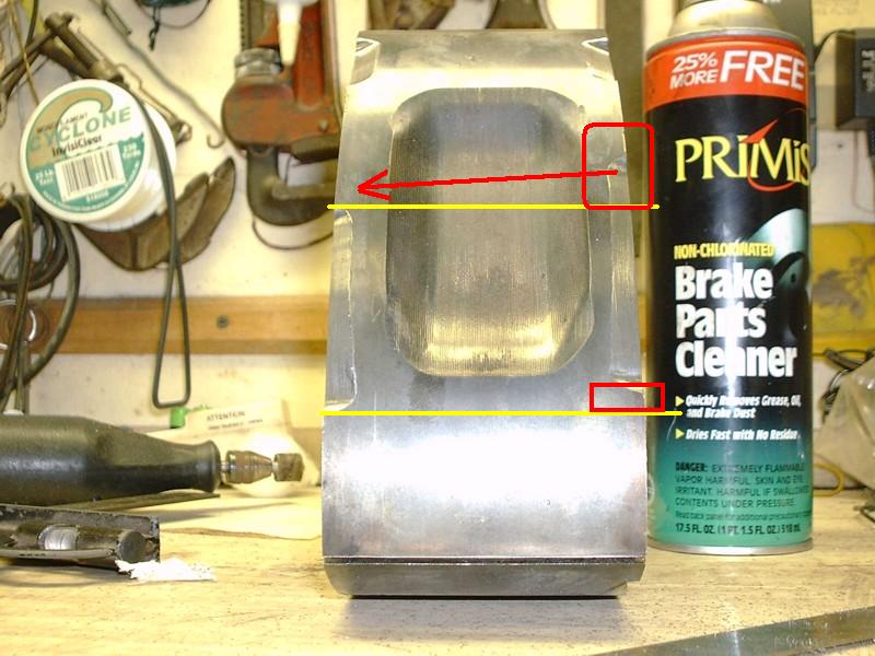
I started out as a machinist-toolmaker back in the 60�s.
It would be a simple job on a 40�s Bridgeport mill with a >16� turntable.
As you can see, you can get pretty close with templates & a Dremmel.
Pretty close is what I can afford.

It would be a simple job on a 40�s Bridgeport mill with a >16� turntable.
As you can see, you can get pretty close with templates & a Dremmel.
Pretty close is what I can afford.
12-15-05, 02:00 PM
#58
Play Well
iTrader: (6)
Join Date: May 2005
Location: Green Bay, WI
Posts: 2,424
Likes: 0
Received 0 Likes
on
0 Posts
I've got to give you some serious cred, man. That porting and the bevels, look amazing. How much time did you spend just templating and doing all the layour for it? And the plastic rotor, I like that idea, mind if I use it? 
As for all the haters, it's DIY for a reason. The objective of DIY is that you are doing it yourself. I don't see why it would blow, so long as he removed the same amount (+/- a few grams) from every rotor face.
Take a nice long drive to North Carolina, then back, and then you'll be closer to stomping it.
12-15-05, 02:15 PM
#59
Seduced by the DARK SIDE
Thread Starter
Join Date: Apr 2001
Location: Orange Park FL (near Jax)
Posts: 7,323
Likes: 0
Received 2 Likes
on
2 Posts
Approximate times:
Layout & templates ~3 hours
Primary & secondary port work ~4 hours
Rotors ~3 hours
And - Runner port matching ~2 hours
Port matching in progress:

Layout & templates ~3 hours
Primary & secondary port work ~4 hours
Rotors ~3 hours
And - Runner port matching ~2 hours
Port matching in progress:
12-15-05, 02:36 PM
#60
IFO Forced Induction Slo
iTrader: (3)
Join Date: Mar 2004
Location: Houston
Posts: 1,315
Likes: 0
Received 0 Likes
on
0 Posts
Originally Posted by wotnartd
As for all the haters, it's DIY for a reason. The objective of DIY is that you are doing it yourself. I don't see why it would blow, so long as he removed the same amount (+/- a few grams) from every rotor face.
Its not DIY just to "do it yourself". Thats dumb. Its DIY because its not in his budget/schedule to send them out to get beveled/balanced. No offense at all, SureShot, I'm behind you on this 99%. I'm sure if you had a machine shop in your area that was willing to bevel the rotors for next to nothing, you would have gone ahead with it through them, as long as it didn't interupt your time schedule.
12-15-05, 02:42 PM
#62
IFO Forced Induction Slo
iTrader: (3)
Join Date: Mar 2004
Location: Houston
Posts: 1,315
Likes: 0
Received 0 Likes
on
0 Posts
Originally Posted by wotnartd
Take a nice long drive to North Carolina, then back, and then you'll be closer to stomping it.
Its also recommended to vary rpms/load durign breakin, hence no long constant rpm drives.
12-15-05, 03:11 PM
#63
Seduced by the DARK SIDE
Thread Starter
Join Date: Apr 2001
Location: Orange Park FL (near Jax)
Posts: 7,323
Likes: 0
Received 2 Likes
on
2 Posts
Originally Posted by wotnartd
And the plastic rotor, I like that idea, mind if I use it?
You realize my rotor bevels are untested, so maybe wait for the results before trying it yourself.
12-15-05, 04:06 PM
#64
Full Member

Join Date: Oct 2005
Location: The Sticks Maine
Posts: 120
Likes: 0
Received 0 Likes
on
0 Posts
As far as going between getting rotors beveled using a cnc mill or manual mill I bet first run times would be pretty damn close. Setting up a rotary table on a manual mill can be tricky unless you have the special stereo indicator to do it quickly. Then mounting the rotor on the table and getting the radius turning concentric with the table would be a pain. Doing so and having it indexed properly would be tough. I cant think of a way to mount the rotor so you would have to re-set for each face. If you could do one setup up really fast, like 5 minutes. There would be 30 minutes of just set up time at and unrealistic pace.
To do it properly on a CNC you would either need to be working from a print or use a CMM to get the dimensions of the rotor. That would only take 10 minutes max. Programing would only be about and hour max. The shape of the port would be kinda tricky to generate unless the software used solid models instead of 2D to 3D drafting. Setup on the CNC mill would be pretty easy. One tool to set up, probably a 3/8 ball mill. Align two points of the rotor parallel with one of the machines axis, probably x. Pick up the center bore for machine zero made fast again with the stereo indicator.
The big thing with having a machie shop do the machining would be you would need to give them a print to work from. A print with dimensions that they could work from. I dont think it would be an easy drawing to do.
As far as balancing I have no idea.
12-15-05, 04:23 PM
#65
IFO Forced Induction Slo
iTrader: (3)
Join Date: Mar 2004
Location: Houston
Posts: 1,315
Likes: 0
Received 0 Likes
on
0 Posts
tonybcrazy, you are absolutly correct. The biggest problem I see is gettting the table path to follow the corner of the rotor, which isn't an exact line. It's not as easy as one might think. There are very few machinist that can program in Houston, much less a machinist/programmer that is actually one of the elitest. Alot of CNC machinist just setup and push buttons, while getting there print from a programmer. I'll see what my brother thinks of this when he gets home, since hes the expert, not me.
12-15-05, 05:48 PM
#66
you guys seem to be overcomplicating the issue, the beveling on the rotors does not need to be exact as the sides of the rotors can be drilled to balance the rotor assembly, just as long as they are close with a dremel and template should be good enough.
drilling the corners of the rotors worked for mazda and even high RPM test engines, why wouldn't it work in this instance?
drilling the corners of the rotors worked for mazda and even high RPM test engines, why wouldn't it work in this instance?
12-15-05, 06:20 PM
#67
Fabricator and builder
Join Date: Jun 2003
Location: Innisfil, Ontario
Posts: 936
Likes: 0
Received 0 Likes
on
0 Posts
Originally Posted by bigdv519
Where's a drunk driver when you need one?
Edit: Hey SureSHot, I just called my brother at his shop. He is a CNC programer/machinist. The first thing he questioned, was how would one follow the curve of the rotor. He said that setting it would take about 30 mins. Machine time wouldn't be very long at all, but he would have to make a program for it, and that takes a little while sometimes. He said that their shop has a $75/hour rate, and a complete job (2 rotors, 12 cuts) could take 4-6 hours.
Edit: Hey SureSHot, I just called my brother at his shop. He is a CNC programer/machinist. The first thing he questioned, was how would one follow the curve of the rotor. He said that setting it would take about 30 mins. Machine time wouldn't be very long at all, but he would have to make a program for it, and that takes a little while sometimes. He said that their shop has a $75/hour rate, and a complete job (2 rotors, 12 cuts) could take 4-6 hours.
You could set the rotors on a rotary table(no pun intended) then offset them enough so that your cutter follows the curve. No need to cnc them.
Brent Guess I should have read further.LOL
Last edited by brent clement; 12-15-05 at 06:27 PM.
12-15-05, 06:26 PM
#68
Fabricator and builder
Join Date: Jun 2003
Location: Innisfil, Ontario
Posts: 936
Likes: 0
Received 0 Likes
on
0 Posts
Originally Posted by tonybcrazy
As far as going between getting rotors beveled using a cnc mill or manual mill I bet first run times would be pretty damn close. Setting up a rotary table on a manual mill can be tricky unless you have the special stereo indicator to do it quickly. Then mounting the rotor on the table and getting the radius turning concentric with the table would be a pain. Doing so and having it indexed properly would be tough. I cant think of a way to mount the rotor so you would have to re-set for each face. If you could do one setup up really fast, like 5 minutes. There would be 30 minutes of just set up time at and unrealistic pace.
To do it properly on a CNC you would either need to be working from a print or use a CMM to get the dimensions of the rotor. That would only take 10 minutes max. Programing would only be about and hour max. The shape of the port would be kinda tricky to generate unless the software used solid models instead of 2D to 3D drafting. Setup on the CNC mill would be pretty easy. One tool to set up, probably a 3/8 ball mill. Align two points of the rotor parallel with one of the machines axis, probably x. Pick up the center bore for machine zero made fast again with the stereo indicator.
The big thing with having a machie shop do the machining would be you would need to give them a print to work from. A print with dimensions that they could work from. I dont think it would be an easy drawing to do.
As far as balancing I have no idea.
To do it properly on a CNC you would either need to be working from a print or use a CMM to get the dimensions of the rotor. That would only take 10 minutes max. Programing would only be about and hour max. The shape of the port would be kinda tricky to generate unless the software used solid models instead of 2D to 3D drafting. Setup on the CNC mill would be pretty easy. One tool to set up, probably a 3/8 ball mill. Align two points of the rotor parallel with one of the machines axis, probably x. Pick up the center bore for machine zero made fast again with the stereo indicator.
The big thing with having a machie shop do the machining would be you would need to give them a print to work from. A print with dimensions that they could work from. I dont think it would be an easy drawing to do.
As far as balancing I have no idea.
12-15-05, 07:12 PM
#69
SureShot, did you press new bearings in the rotors???no... then that thing needs little breakin so go out and put the pedal to the metal and if we read in the paper tomorrow that a man was brought to the emergancy room because he had a rotor up his butt then we will know if it blew up... im just joking around... I love the bench top machine shop work... I might just do that to my rotors
On another note it would be interesting to see how balanced they are... to see how close to the +/- tolerance of the factory spec they are
On another note it would be interesting to see how balanced they are... to see how close to the +/- tolerance of the factory spec they are
12-15-05, 07:18 PM
#70
TIME & MILEAGE RECOMMENDATIONS
**********DYNO HOURS ************MILEAGE
RPM NEW BEARINGS OLD BEARINGS NEW BEARINGS OLD BEARINGS
1500 0.5********** - ********* - ***************-
2000 0.5********** 0.5********* - *************-
2500 0.5********** - *********** - *************-
3000 0.5********** - *********** - *************-
4000 1.0********** 0.5 ********* - *************-
5000 1.0********** 0.5 ******** 60 ************-
6000 1.5********** 0.5 ********* 60 ***********25
6500 1.5********** 0.5 ********* - ************* -
7000 - *********** - ********** 60 ***********25
8000 - *********** - ********** 60 ***********25
8500 - *********** - ********** 60 *********** 25
TOTAL 7.0********** 2.5*********300 ************100
 sorry its not very st8..but that is what is on the mazda speed motor sports for braking in a motor
**********DYNO HOURS ************MILEAGE
RPM NEW BEARINGS OLD BEARINGS NEW BEARINGS OLD BEARINGS
1500 0.5********** - ********* - ***************-
2000 0.5********** 0.5********* - *************-
2500 0.5********** - *********** - *************-
3000 0.5********** - *********** - *************-
4000 1.0********** 0.5 ********* - *************-
5000 1.0********** 0.5 ******** 60 ************-
6000 1.5********** 0.5 ********* 60 ***********25
6500 1.5********** 0.5 ********* - ************* -
7000 - *********** - ********** 60 ***********25
8000 - *********** - ********** 60 ***********25
8500 - *********** - ********** 60 *********** 25
TOTAL 7.0********** 2.5*********300 ************100
sorry its not very st8..but that is what is on the mazda speed motor sports for braking in a motor
Last edited by 81gsl12a; 12-15-05 at 07:22 PM.
12-15-05, 07:26 PM
#71
I do have one question regarding the bevel... or more like an observation. The bevels are not the same and i assume thats becuase each side was "matched" to ther perspective port ie primary or secondary... wouldnt you want to match these beveles to each other rather then the port they match to for better balanacing
12-16-05, 06:58 AM
#73
Seduced by the DARK SIDE
Thread Starter
Join Date: Apr 2001
Location: Orange Park FL (near Jax)
Posts: 7,323
Likes: 0
Received 2 Likes
on
2 Posts
Originally Posted by BASTARD
I do have one question regarding the bevel... or more like an observation. The bevels are not the same and i assume thats becuase each side was "matched" to ther perspective port ie primary or secondary... wouldnt you want to match these beveles to each other rather then the port they match to for better balanacing
There are several variables here.
First: I wanted the primaries to open first to keep as much low end torque as I could.
From what I see, opening the primaries first was what Mazda�s R&D intended also.
That appears to have worked. My butt likes it, hopefully a dyno chart will verify it.
Second: Front-to-rear balance is not as critical as rotational balance (within limits).
Front-to-rear loading is already uneven because you have timing gear load on one side & a bearing on the other side of the rotor during the power stroke. That�s one reason why the bearings are so big.
The primary side can be slightly heavier than the secondary side as long as all three faces are identical.
Third: This is a street setup, not a race setup, so time & money is short.
Break-in: What is extending my break-in is the apex seal grooves. This engine had 3-piece seals and the top piece was rocking in the groove. The grooves are in spec, but not exactly flat, so I have to give the 2-piece seals some time to seat in before leaning on them.
Last edited by SureShot; 12-16-05 at 07:22 AM.
