S5 Turbo Engine Harness Placement
 09-07-10, 06:32 PM
#1
Rider of the Sky
Thread Starter
S5 Turbo Engine Harness Placement
I'm putting together an S5 Turbo motor that I bought awhile back, sans engine harness, to finally put in my car. Thing is, while I now have a harness, I can't figure out how to put the thing on. I have a very rough idea from the FSM and Haynes manuals, but not good enough to fit correctly with the vacuum rack or even tell the primary and secondary injector connectors apart.
Does anyone have or know of a good diagram, or some images with the intercooler removed so I can see the ups and downs of how it threads across the top of the motor?
Does anyone have or know of a good diagram, or some images with the intercooler removed so I can see the ups and downs of how it threads across the top of the motor?
 09-07-10, 07:00 PM
#2
Rotary Enthusiast
iTrader: (14)

Join Date: Mar 2009
Location: the dalles
Posts: 1,161
Likes: 0
Received 0 Likes
on
0 Posts
well with my s4 it really just slug across the front then wrapped around the side and ended wrapping around the rear of the engine. as far as telling the different plugs apart cant helpy ou there
09-08-10, 07:31 PM
#3
Rider of the Sky
Thread Starter
I think I've got the general idea since the harness still has the shape from the previous engine it was recently on, but I'm still stumped by the injector clips. There's two configurations that reach, both with pros and cons that have me unable to make up my mind.
<table border="2">
<tr>
<td><b>Config A</b>:</td>
<td>and <b>Config B</b>:</td>
</tr>
<tr>
<td>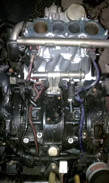 </td>
</td>
<td>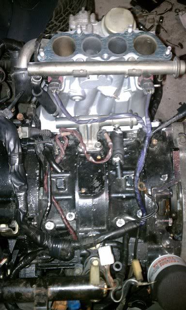 </td>
</td>
<tr>
</table>
I added a color highlighting to make the two sections of the harness easier to tell apart. <b>Config A</b> fits the best with all the sharp bends in the wire resting against things that would have bent them in the first place, but I would expect that the white marker tape (note the white marker tape next to the "red" section's injector clips) and wire colors would be fuel rail specific, not rotor specific, which would have <b>Config B</b> make the most sense.
Could somebody that's seen the top of a turbo motor set me straight? No guesswork please.
<table border="2">
<tr>
<td><b>Config A</b>:</td>
<td>and <b>Config B</b>:</td>
</tr>
<tr>
<td>
</td><td>
</td><tr>
</table>
I added a color highlighting to make the two sections of the harness easier to tell apart. <b>Config A</b> fits the best with all the sharp bends in the wire resting against things that would have bent them in the first place, but I would expect that the white marker tape (note the white marker tape next to the "red" section's injector clips) and wire colors would be fuel rail specific, not rotor specific, which would have <b>Config B</b> make the most sense.
Could somebody that's seen the top of a turbo motor set me straight? No guesswork please.
09-09-10, 09:20 PM
#5
Retired Moderator, RIP
iTrader: (142)
Join Date: Sep 2005
Location: Smiths Falls.(near Ottawa!.Mapquest IT!)
Posts: 25,581
Likes: 0
Received 131 Likes
on
114 Posts
use B.
On pic 'A' It looks like you are crossing the wiring for the Injectors.
The Injectors should Run off the same Piece of harness for the Leading,,and then the secondaries get hooked off another RUN of the Harness,.
they don't get Fed by one spot for ONE leading injector then "way further down" at another location for L2(second leading injector).
Remember you can mix up the Leading and secondary wiring(.as in Put L1 to L2,or L2 to L1) as they "batch fire",BUT you can't put a Leading harness wire on a Secondary Injector or Vice Versa.the engine will "let you know" IF you do that.Trust me.
09-10-10, 01:41 PM
#6
Rider of the Sky
Thread Starter
It was Config A. In hindsight my lines of thinking for promoting "B" was my familiarity with the leading/trailing spark plug configuration, where the pulse patterns are completely different. The injectors are probably a far less complicated firing pattern (no intermittant overlap).
Thanks for the nudge in a different direction, RotaryRocket88. I was frustrated and not thinking of alternate ways to attack the problem. While I can't find a diagram of the harness anywhere, the ECU pinout only took about three minutes.
Thanks for the nudge in a different direction, RotaryRocket88. I was frustrated and not thinking of alternate ways to attack the problem. While I can't find a diagram of the harness anywhere, the ECU pinout only took about three minutes.

Thread
Thread Starter
Forum
Replies
Last Post
trickster
2nd Generation Specific (1986-1992)
25
07-01-23 04:40 PM
KAL797
Test Area 51
0
08-11-15 03:47 PM