
rats crap.. need some identification..
 05-08-04, 06:16 PM
#1
Rotary Enthusiast
Thread Starter
Join Date: Aug 2002
Location: MO
Posts: 850
Likes: 0
Received 0 Likes
on
0 Posts
rats crap.. need some identification..
im removing the rats nest .. took the uim and tb off and i just wanted some positive identification on what things are and what needs vacuum. plz dont say "look in fsm" cause the vacuum diagram doesnt tell you everything you need to know, and its hard to follow lines through the spider 


pleeease correct me if im wrong on all of these, because i want to make sure all of these are what i think.
1. egr, needs vacuum line unless removed
2. this hose goes to the back of the engine somewhere near the egr, no idea if it needs to be ran to something or not?
3. oops
4. fuel pressure regulator.. needs vacuum. after throttle plates not before.
5. part of cold startup assist?
6. pulsation damper. want to put on a banjo bolt. is it located in the same place on an na?
7. what in the world is this.. and does it use vacuum? i think the lines going to the sides of it run to the omp..
also, if you can add to this list of things that need vacuum when installed. egr, boost sensor, bov, brake booster, fpr, boost gauge. thats all i can think of right now.
thanks all.
 05-08-04, 06:33 PM
#2
Rotary Enthusiast
Thread Starter
Join Date: Aug 2002
Location: MO
Posts: 850
Likes: 0
Received 0 Likes
on
0 Posts
also on the TB mod on fc3s pro.. what is the NPT plug used for.. and can u just cap the coolant nippe on the top of the engine that the TB used to run to after this is done??
05-08-04, 06:42 PM
#3
Full Member
Join Date: Oct 2003
Location: Canada
Posts: 94
Likes: 0
Received 0 Likes
on
0 Posts
1) Take off the EGR... if its clogged, ditch it... if its not... ditch it anyway if you want and block it off.
2) It's not too clear... but it kind of looks like the brake booster? if so leave it.
4) It needs vacuum.. there should be a little nipple on the inside of the LIM that faces towards the firewall a bit... use that.
5) I just put a block off plate on that... (mind u I have no emmisions, accessories, twin scroll, or oil injectors)
6) Should be in the same place.
7) That is an oil injector... if u are premixing, you can ditch the OMP and block it off, and take out those injectors and put bolts in place. It does use vacuum.
All I have is the FPR line from the LIM, brake booster, and the line from the LIM to the boost sensor/boost gauge.
Someone else can correct me if I'm wrong.
05-08-04, 09:52 PM
#5
Full Member
Join Date: Oct 2003
Location: Canada
Posts: 94
Likes: 0
Received 0 Likes
on
0 Posts
OK... I did that mod too.. but I did it a bit differently.
The throttle plates you took out... were connected to a rod that went through the sides of the throttlebody. If that isn't plugged air will leak out.. and it wont run long. The plug is used to seal the hole... but you have to tap it. What I did.. was take a bolt, a nut, and a rubber washer... Put the bolt through the hole facing out with the rubber washer sealing it, then bolted it tight. It is ghetto, but it works, and I didn't have to buy a tap and die set.
And about the coolant... I found some hose that fit from the local autoparts store and ran the hose from that coolant nipple on the top of the motor to the back of the waterpump. This way the coolant has an even flow. It's a tight fit, but it seems to be holding up fine.
05-08-04, 10:09 PM
#6
Compression Tester Guy
iTrader: (3)
Join Date: Apr 2003
Location: Houston, TX
Posts: 1,010
Likes: 0
Received 0 Likes
on
0 Posts
For TB mod no tap and die set is necessary, just fill the secondary throttle plate rod holes with JB weld. Put tape inside the TB over the holes and fill them from the outside. Once the JB weld cures, remove the tape. Perfectly smooth inside and it doesn't look ghetto.
05-08-04, 10:11 PM
#7
I'm a boost creep...
Join Date: Jan 2002
Location: Auckland, New Zealand
Posts: 15,608
Likes: 0
Received 8 Likes
on
8 Posts
Here's what will be left.

The info Spool_TSI posted is correct, except the oil injectors suck air from before the throttle, they do not see vacuum.
As for the TB mod, the instructions are pretty clear what to do with the plugs. Where's the confusion?
The info Spool_TSI posted is correct, except the oil injectors suck air from before the throttle, they do not see vacuum.
As for the TB mod, the instructions are pretty clear what to do with the plugs. Where's the confusion?
Trending Topics
05-09-04, 01:33 AM
#8
Full Member
Join Date: Oct 2003
Location: Canada
Posts: 94
Likes: 0
Received 0 Likes
on
0 Posts
Originally posted by TwistedRotors
For TB mod no tap and die set is necessary, just fill the secondary throttle plate rod holes with JB weld. Put tape inside the TB over the holes and fill them from the outside. Once the JB weld cures, remove the tape. Perfectly smooth inside and it doesn't look ghetto.
For TB mod no tap and die set is necessary, just fill the secondary throttle plate rod holes with JB weld. Put tape inside the TB over the holes and fill them from the outside. Once the JB weld cures, remove the tape. Perfectly smooth inside and it doesn't look ghetto.
05-09-04, 08:35 AM
#11
Rotary Enthusiast
Thread Starter
Join Date: Aug 2002
Location: MO
Posts: 850
Likes: 0
Received 0 Likes
on
0 Posts
the confusion on my part was.. why use jb weld and the NPT plug. is it safe just to use jb weld? also you said the oil injectors suck air before the throttle body.. but on the diagram they are after it, it looks like. where do i have them suck air from?
05-09-04, 08:41 AM
#12
777** The Anti-rice
Join Date: Sep 2002
Location: Seattle, WA
Posts: 2,100
Likes: 0
Received 0 Likes
on
0 Posts
Originally posted by imloggedin
the confusion on my part was.. why use jb weld and the NPT plug. is it safe just to use jb weld?
the confusion on my part was.. why use jb weld and the NPT plug. is it safe just to use jb weld?
Ive heard of people putting tape on the inside of the TB, then filling the hole with JB weld. This, imo, is completely dumb. The chances of JB weld being sucked into the engine are much higher..
Either JBweld a bolt in, or tap the hole and fill it with jb weld (I dont recommend this either), or just use helicoil.
You can get a helicoil kit for about 30some bucks, expensive ****, but its awesome.
Last edited by DEZERTE; 05-09-04 at 08:46 AM.
05-09-04, 03:02 PM
#13
Rotary Enthusiast
Thread Starter
Join Date: Aug 2002
Location: MO
Posts: 850
Likes: 0
Received 0 Likes
on
0 Posts
what about the oil injectors??? do i need vacuum running directly to them. or does the vacuum run to the omp? agghh confusing.. and what about the egr. i know it needs vacuum. anyone know what the thing is in that pic thats unnamed?
Last edited by imloggedin; 05-09-04 at 03:06 PM.
05-09-04, 04:54 PM
#14
I'm a boost creep...
Join Date: Jan 2002
Location: Auckland, New Zealand
Posts: 15,608
Likes: 0
Received 8 Likes
on
8 Posts
Originally posted by imloggedin
what about the oil injectors??? do i need vacuum running directly to them. or does the vacuum run to the omp?
what about the oil injectors??? do i need vacuum running directly to them. or does the vacuum run to the omp?
and what about the egr. i know it needs vacuum.
anyone know what the thing is in that pic thats unnamed?
05-10-04, 12:18 PM
#15
Rotary Enthusiast
Thread Starter
Join Date: Aug 2002
Location: MO
Posts: 850
Likes: 0
Received 0 Likes
on
0 Posts
thanks nz, actually .. #2.. anyone know what that is?
also i guess im having trouble understanding.. the oil injector air bleed.. in the diagram its getting vacuum from the uim. but you said it should not get vacuum.. how can the UIM have non vacuum air?
im just really confused about the oil injector vacuum air crap.. do the lines run to the OMP? do ANY lines run directly to the injectors? (im at work so i cant go look at any of this stuff)
thanks
05-10-04, 12:44 PM
#16
Rotary Enthusiast
Thread Starter
Join Date: Aug 2002
Location: MO
Posts: 850
Likes: 0
Received 0 Likes
on
0 Posts
i guess my biggest question is.. does a line run to the nipple on top of the oil injectors from the 1 to 4 way adapter deal? because when i took my UIM nothing was running to the injectors. and the vacuum diagram i dont see anything either. : :
:
:
05-10-04, 02:17 PM
#17
5. Sub Zero assist. Totally useless. I think Mazda even posted a service update to remove it? Remove it and block it off. Now you have more room. It will also have a bottle for coolant on the passenger firewall/fender area. Toss it. It has nothing to do with emissions.
Here is a pic of my S5 block with emissions removed but still keeping the FPR hotstart solenoid(seen on the left IC bracket)

 Kind of helpfull pic
Here is my Vac rack setup. I have kept the FPR solenoid and the PCV system.
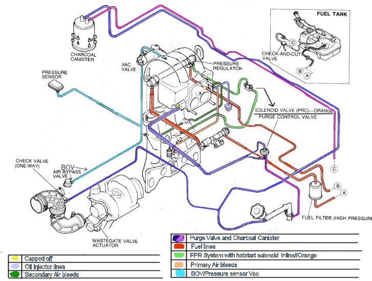 This is S5 so you will not have the secondary injector airbleed on the end of the UIM. Everything else is pretty much the same.
This is for use without the S4 Twin scroll or S5 boost controller.
Here is a pic of my S5 block with emissions removed but still keeping the FPR hotstart solenoid(seen on the left IC bracket)
Kind of helpfull pic Here is my Vac rack setup. I have kept the FPR solenoid and the PCV system.
This is for use without the S4 Twin scroll or S5 boost controller.
05-10-04, 04:15 PM
#20
I'm a boost creep...
Join Date: Jan 2002
Location: Auckland, New Zealand
Posts: 15,608
Likes: 0
Received 8 Likes
on
8 Posts
It's not vacuum. The oil nozzles line is bigger than the other vac lines, and it connects to the big nipple on the rear of the UIM behind the TB. Passages within the UIM, spacer and TB feed it air from in front of the throttle. That's how it is stock and that's the only way it'll work properly.
