Important intake manifold info
 08-22-07, 11:32 AM
#1
Full Member
Thread Starter
Join Date: Jul 2005
Location: texas
Posts: 198
Likes: 0
Received 0 Likes
on
0 Posts
Important intake manifold info
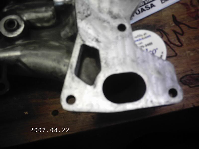
I dont know if this has been posted before, but in all my searches, I have never found any information about this. I am looking into porting a T2 LIM to fit onto a NA block. Everything I have been told is that you DO NOT have to add metal to the manifold, and I found out today that this is completely fasle.
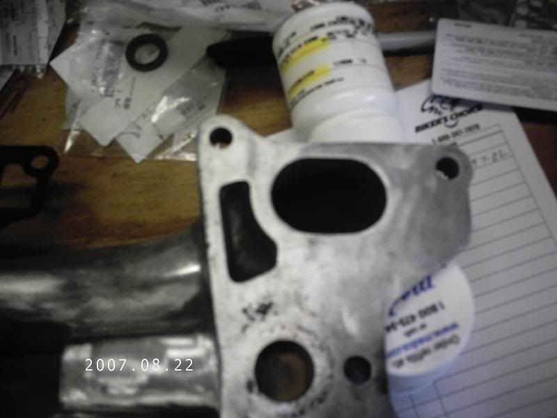
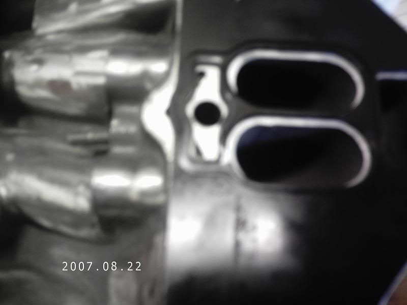
The left side of the manifold if you are looking at the engine side.
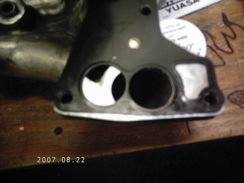
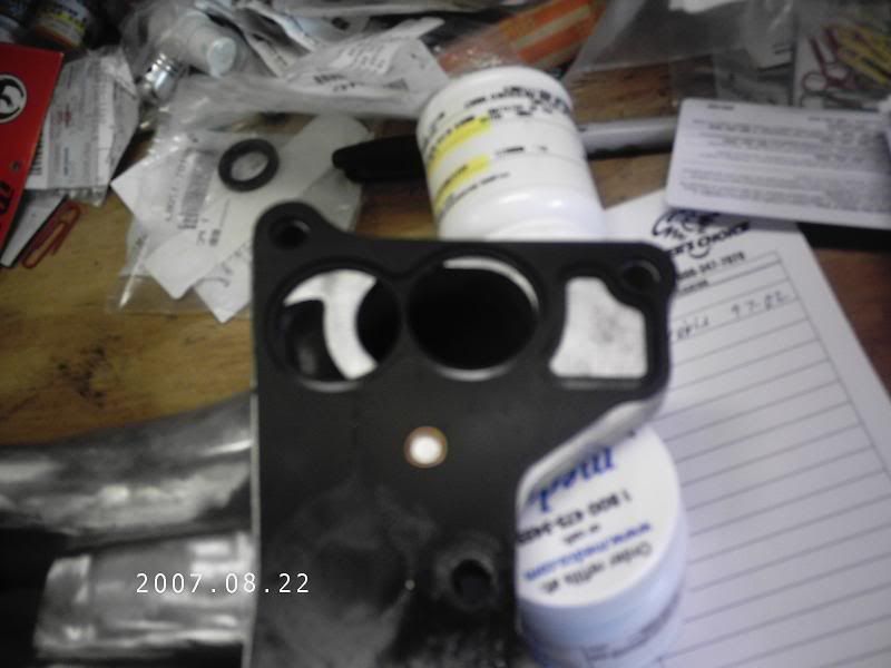
And the right side.
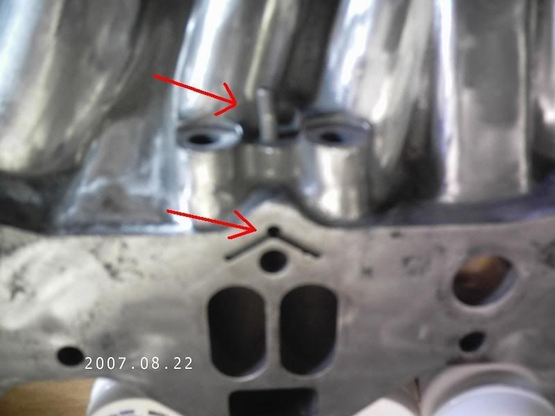
And in the middle, there is a place for vacuum that will also have to be filled in.
Im sure this will help someone that is thinking of putting a T2 LIM on their NA motor to do a turbo swap.
The left side of the manifold if you are looking at the engine side.
And the right side.
And in the middle, there is a place for vacuum that will also have to be filled in.
Im sure this will help someone that is thinking of putting a T2 LIM on their NA motor to do a turbo swap.
 08-22-07, 11:58 AM
#2
HAILERS

Join Date: May 2001
Location: FORT WORTH, TEXAS,USA
Posts: 20,563
Likes: 0
Received 22 Likes
on
20 Posts
You should not fill in the passage for the fuel injector air bleeds.
Must be a series five manifold. Series four is a bit different and you have to fill in a void PLUG match the manifold to the gasket.
Must be a series five manifold. Series four is a bit different and you have to fill in a void PLUG match the manifold to the gasket.
08-22-07, 12:49 PM
#4
Full Member
Thread Starter
Join Date: Jul 2005
Location: texas
Posts: 198
Likes: 0
Received 0 Likes
on
0 Posts
and to add to the fun, i noticed while i was marking mine on where the new ports will have to be, that there is not enough metal on the outside of the manifold. you will have to add metal to the sides for the front and rear of the manifold.
08-22-07, 02:50 PM
#5
HAILERS
Join Date: May 2001
Location: FORT WORTH, TEXAS,USA
Posts: 20,563
Likes: 0
Received 22 Likes
on
20 Posts
Attached is a jpg of a series four turbo intake manifold and the area that has to be filled in can almost be seen. I filled it with plumbers solder. Melted it in a tin cup and poured it. Had sand filling the intake holes to prevent them from getting filled up. Sanded the solder flush with the mating surface.
And please, no body try to tell me the solder will MELT when the engine is running. Please, nobody be silly like that.
Air bleeds are what your injectors sit in. Primary injectors on a series four. the hole with the VEE cut around it, mates with the intermediate housing. There is a hole in the intermediate housing opposite that VEE hole. That hole leads to both primary injector air bleeds just below the fuel injectors themselves.
08-22-07, 03:33 PM
#6
HAILERS
Join Date: May 2001
Location: FORT WORTH, TEXAS,USA
Posts: 20,563
Likes: 0
Received 22 Likes
on
20 Posts
http://www.mazdatrix.com/c-6.htm
Air bleeds are shown in the above site. The small hole in the intake manifold leads to a small hole opposite the items shown in the site above.
The nipple on the intake manifold should NOT go to a vacuum source. It should go to one of the nipples on the back of the throttle body that supplys metered air to that nipple i.e. not a vacuum source.
Not all nipples on a throttle body are vacuum. Some/most are from a source PRIOR to the throttle plates, meaning no vacuum on them.
08-22-07, 04:27 PM
#7
Full Member
Thread Starter
Join Date: Jul 2005
Location: texas
Posts: 198
Likes: 0
Received 0 Likes
on
0 Posts
Attached is a jpg of a series four turbo intake manifold and the area that has to be filled in can almost be seen. I filled it with plumbers solder. Melted it in a tin cup and poured it. Had sand filling the intake holes to prevent them from getting filled up. Sanded the solder flush with the mating surface.
Trending Topics
08-22-07, 06:27 PM
#8
HAILERS
Join Date: May 2001
Location: FORT WORTH, TEXAS,USA
Posts: 20,563
Likes: 0
Received 22 Likes
on
20 Posts
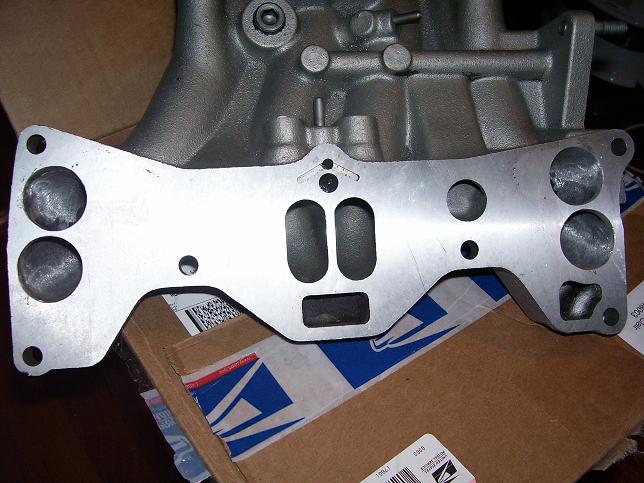
I filled the depressions with the solder. Then layed the gasket over the manifold like you show, and scribed a line around the port openings.
I used a Dremel with a barrel sander of 80 grit and the material came off pretty quick. On the outboard side the material is thinner on a series four. So I got a number 30 or 40 drill bit and drilled a hole in that part of the duct. Every once and a while I'd check the thickness of the material there as I was grinding. I'd check just by inserting that drill bit in the hole and putting a finger on the drill bit as it came thru to the intake side to keep it flush with the inside of the duct. Made a mark on the drill bit where it was flush with the outside of the duct and pulled the bit out. From the mark to the end of the bit is how much material is left to grind on.
I think your manifold looks much different than the series four did. I did not take a picture of the series four prior to grinding. Well I did, but that picture got deleted with most the jps I've attached in the past.
That square looking hole above the round intake hole was not there on the series four turbo intake manifold, if memory serves. And memory does serve in this case.
I'll look around for jpgs on the other site.
Here: http://forum.teamfc3s.org/showthread.php?t=37694 but I think those are series four manifolds. And they used some plastic filler to fill the void areas. Still looking for a jpg of a series four turbo manifold without the voids filled. Looking.
Last edited by HAILERS; 08-22-07 at 06:33 PM.
08-22-07, 08:44 PM
#10
Full Member
Thread Starter
Join Date: Jul 2005
Location: texas
Posts: 198
Likes: 0
Received 0 Likes
on
0 Posts
for me, the reason im using the T2 LIM is that i am going turbo on my 1gen GSLSE. im using the turbo LIM and a racing beat upper manifold to bolt on a weber side draft carb. the NA LIM will not clear the stock T2 turbo and manifold (which im using at first) without a spacer.
for almost everyone else, im sure it would be so they could go turbo for cheaper. using the NA block and all the turbo intake manifold, wiring, and ecu so they will not have to do the complete swap.
and as a side note, im dont want to hear carb vs efi arguments. my car was already carb when i got it and i plan on keeping it that way for a long time.
 08-23-07, 09:17 AM
#13
HAILERS
Join Date: May 2001
Location: FORT WORTH, TEXAS,USA
Posts: 20,563
Likes: 0
Received 22 Likes
on
20 Posts
Attached is a jpg of a series four turbo intake manifold and the area that has to be filled in can almost be seen. I filled it with plumbers solder. Melted it in a tin cup and poured it. Had sand filling the intake holes to prevent them from getting filled up. Sanded the solder flush with the mating surface.
And please, no body try to tell me the solder will MELT when the engine is running. Please, nobody be silly like that.
Air bleeds are what your injectors sit in. Primary injectors on a series four. the hole with the VEE cut around it, mates with the intermediate housing. There is a hole in the intermediate housing opposite that VEE hole. That hole leads to both primary injector air bleeds just below the fuel injectors themselves.
And yes, that japan 2LA looks nice.
08-23-07, 10:30 AM
#14
Full Member
Thread Starter
Join Date: Jul 2005
Location: texas
Posts: 198
Likes: 0
Received 0 Likes
on
0 Posts
have you used it yet HAILERS? and if so, how well does that solder hold up? i mentioned the idea to my dad, and he said that it would get too hot and melt. you said it wont melt, and i was wondering if you know that from experience or just an educated guess. i dont know the melting point of solder.
and honestly, it doesnt matter what it looks like on the outside as long as it preforms. with a car, beauty is the performance and dyno sheet, not the looks (especially on the inside).
and honestly, it doesnt matter what it looks like on the outside as long as it preforms. with a car, beauty is the performance and dyno sheet, not the looks (especially on the inside).
08-23-07, 03:50 PM
#15
HAILERS
Join Date: May 2001
Location: FORT WORTH, TEXAS,USA
Posts: 20,563
Likes: 0
Received 22 Likes
on
20 Posts
I seriously doubt it will melt. Remember, a lot of new cars use plastic intake manifolds. This is not an exaust manifold.
And look at that link I attached in an earlier post. Those people use a plastic filler material like Devcon or JBWELD. There's no way I'm going to use JBWELD in an intake and have it flake off when it gets older.
And no, i've not finished this little project. I've two turbo cars and one 86 non turbo. Frankly speaking, I enjoy driving the non turbo car. It's a change of pace from the other two. I rebuilt an engine and it's just sitting there on the end of a engine hoist chain for the better part of a year because I can't convince myself to put it in the non turbo car. Like I said, I enjoy the non turbo car. This thread might force me to install it..........or put it in one of the turbo cars. Hmmmm. Cheaper and easier, just time consuming and takes me away from my boat building project.
I've never had a series five and I can't figure out just what those two upper holes in your turbo manifold are for. Do you have any idea? Anybody. Just curious. I don't think it's for ACV because that's what the rectangular hole in the middle of the intake is for (the one below the two oval intake passages). And series five have no EGR so they're not EGR passages.
Nope. I don't think it'll melt. It's an intake manifold and if the temps ever got hot enough to do that, the engine would be toast/ruined/kaput by that time.
EDIT: I meant to mention something. The series four intake manifold is different than yours. That area where I filled in with solder, well it's a shallow depression more than anything. Maybe a 1/4 inch deep in some areas near the intake hole. And the solder was poured as a solid block. Not in dribs and drabs at a time. So it's a solid piece of metal trapped b/t the intake manifold and the *block* once bolted on. It's not going to flake off like maybe the JBWELD type stuff MIGHT. Never ever read anything about anybody actually having problem with the JBWELD breaking of though. Just the thought bothers me.
Last edited by HAILERS; 08-23-07 at 03:58 PM.

Thread
Thread Starter
Forum
Replies
Last Post