Heater Controller/Logicon not working
#1
Heater Controller/Logicon not working
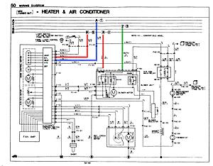
HELP! This is the last important step in getting my EV conversion to work! I have been through a lot so far to try and figure this out. I've included some pictures.
Picture 1:
So the wires I have marked in red appear, as far as I can tell, to be getting the proper 12v. The wire marked in green is getting only about 0.6v when key is in position 1. Don't know if that is normal or not.
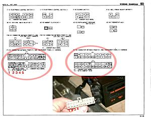
The wire marked in blue, I can't properly identify. Here is why.
Picture 2:
What the heck?!?! This harness doesn't make sense...the harness(es) marked "Connector between front and instrument panel" have 5 leads on each side...but the actual tail from the instrument panel only has 4?!?!?! Come on, really?! Are you telling me that the tail harness for the instrument panel is not ont he heater & air conditioner wiring diagram? So where is it? And more importantly, where ARE those connectors that are listed on the diagram? It doesn't make sense.
#6
Theoretical Tinkerer
iTrader: (41)
Joined: Oct 2003
Posts: 1,590
Likes: 47
From: Norcal/Bay Area, CA
You're not looking at the same connector. The "Body electrical system" section of the FSM has information about the logicon around page 100. It's is difficult to decipher without the logicon tester, but you may be able to figure something out. Good luck.
Trending Topics
#11
Pay attention to the info provided by HAILERS.
https://www.rx7club.com/showthread.p...sistor+hailers
https://www.rx7club.com/showthread.p...sistor+hailers
#12
Pay attention to the info provided by HAILERS.
https://www.rx7club.com/showthread.p...sistor+hailers
https://www.rx7club.com/showthread.p...sistor+hailers
And if it isn't there, where is it in the diagrams?
#13
Look carefully at the second picture and you will understand my confusion. The tail that sticks out of the logicon is either misrepresented, or not represented at all in the diagrams. That is why this has become so frustrating and confusing.
#14
Pay attention to the info provided by HAILERS.
https://www.rx7club.com/showthread.p...sistor+hailers
https://www.rx7club.com/showthread.p...sistor+hailers
Thanks all.
*EDIT: Thinking about it, there may have been a short in my original logicon that caused the fault, as it works with the new logicon and the fuse being replaced.
Last edited by Frankencar1; 03-24-12 at 07:29 PM.
Thread
Thread Starter
Forum
Replies
Last Post
turbo-minivan
General Rotary Tech Support
69
02-04-16 12:29 AM
KAL797
Test Area 51
0
08-11-15 03:47 PM


