Budget V-mount build
#1
Budget V-mount build
Basically, I'm converting my front mount IC to a V-mount, mainly to get SSM legal. I'm becoming ok at this auto-x thing and need to get put my bumper core back in. This, coupled with some boredom over xmas break, led to a somewhat spontaneous V-mount conversion. I'll get some pics of the mounts tomorrow once I tear it all down to get the radiator neck re-welded.
Budget: basically zero (a case of beer for the welding, about $50 for aluminum stock, $30 for braided hose, and $40 for some elbows)
Existing stuff: patchwork FMIC setup, RB oil lines and a Koyo.
Feel free to rip this to shreds, its hardly a Speedmachines quality build.

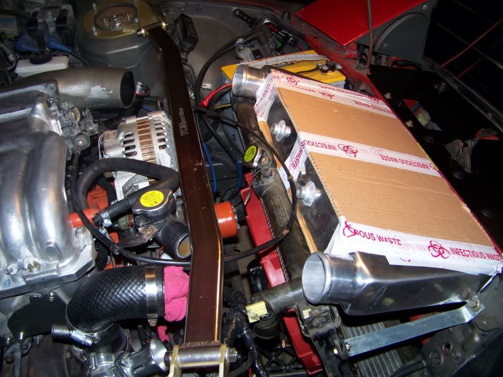
Basic overview. The MAF is in the lower left corner and route down through the old piping path. Turbo side piping is above it (still waiting on the elbow). IC is just resting and not attached yet. You can see the angle bracket on the bottom of it that will eventually bolt it to the original radiator support.

Lower passenger side front. Shows oil cooler mockup and intake. Not pictured, but I re-used the long RB line as the new shorter line, and stole the fittings off the short line and put them on the new super long (like 4') rear line.

View of radiator setup. It has about an inch clearance from the nose of the water pump pulley. Solid mount should prevent the engine from jumping into it. I think I'm gonna cut out a little "guard" piece out of the spare stock, not that it will help with a major impact, but might prevent damage from any light touch.

This is the side of the ducting. These pieces are 1/16" Aluminum and alot beefier than they look. Bolted on is a pair of 1/8", 3/4" x 3/4" Aluminum angle stock. 2 of these are welded together to form the upper mount. One of the legs of the "L" is cut and bent to mate with the stock radiator mount. Also, one the legs is partially milled down to provided both a seat and hood clearance for the IC. Will have better pictures tomorrow. The lower radiator mount is similarly designed.
Comments welcome, remember its a budget build.
Budget: basically zero (a case of beer for the welding, about $50 for aluminum stock, $30 for braided hose, and $40 for some elbows)
Existing stuff: patchwork FMIC setup, RB oil lines and a Koyo.
Feel free to rip this to shreds, its hardly a Speedmachines quality build.

Basic overview. The MAF is in the lower left corner and route down through the old piping path. Turbo side piping is above it (still waiting on the elbow). IC is just resting and not attached yet. You can see the angle bracket on the bottom of it that will eventually bolt it to the original radiator support.

Lower passenger side front. Shows oil cooler mockup and intake. Not pictured, but I re-used the long RB line as the new shorter line, and stole the fittings off the short line and put them on the new super long (like 4') rear line.

View of radiator setup. It has about an inch clearance from the nose of the water pump pulley. Solid mount should prevent the engine from jumping into it. I think I'm gonna cut out a little "guard" piece out of the spare stock, not that it will help with a major impact, but might prevent damage from any light touch.

This is the side of the ducting. These pieces are 1/16" Aluminum and alot beefier than they look. Bolted on is a pair of 1/8", 3/4" x 3/4" Aluminum angle stock. 2 of these are welded together to form the upper mount. One of the legs of the "L" is cut and bent to mate with the stock radiator mount. Also, one the legs is partially milled down to provided both a seat and hood clearance for the IC. Will have better pictures tomorrow. The lower radiator mount is similarly designed.
Comments welcome, remember its a budget build.
#3
#5
That was my original plan, but I end up with a REALLY tight bend around the driver's strut tower. Eventually I'd like to get an IC with the inlet and outlet pointing towards the rear of the car, which would eliminate even more piping.
#7
I just bought a new intercooler that is similar to what your describing. I think most guys have seen BLUETII's and TTT's wicked HMIC setups, I will be attempting to mimic these.
BLUETII
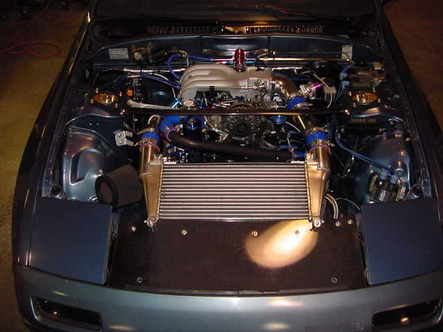
TTT
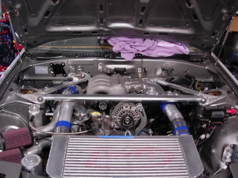
I just ordered this guy here:
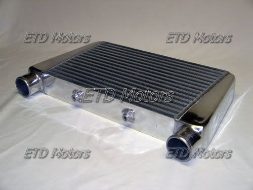
I like what your doing for the shrouding though, keep us posted.
BLUETII

TTT

I just ordered this guy here:

I like what your doing for the shrouding though, keep us posted.
Trending Topics
#8
I've talked to BlueTII a bit about his setup. It was really my model. I guess I was just trying to work with what I had layin around. I figure I'll improve this as I get some more free time and money. It should be fine for the race season this summer though, I'll clean it up next winter when the engine comes out for a freshening.
#9
I think what your doing is going to work well. I kinda got sucked into an intercooler upgrade when I decided to swap to FD intake manifolds, I didn't expect to get into it this deep. I had to get an e-fan and controller, you're making out good using what you already have.
#10
So I went home with some friends last weekend and finished the build. I wish a few more technical pictures had been taken, but I'll post what we got.
Over the past 2 weeks, I cut off the bend in the upper radiator neck, and got a bead welded onto the pipe. I also had 2 upper tabs welded onto the intercooler. First order of business was to mock up the radiator so we could start the fan mounting.

I had originally intended to mount the fan with the 4 tabs I had welded onto the side ducting. If I ever switch to dual 12" Permacools this might still be true. With the current fan though, we had to improvise a little bit.

The extreme side mounting of the fan was dictated by main pulley clearance.

It didn't quite fit as designed. My advice: start with a straight car, and do the welding less than 300 miles away from the chassis. This pic also shows the lower mount for the radiator quite well. It bolts onto the bottom of the that bracket (out of the picture), and then the bent tab bolts onto the stock mount to the chassis.

This bend proved a bit tight for the bendy-hose. Does anyone know where I can get custom hoses done for this? It doesn't leak but looks a bit ghetto.

This pic shows the upper tabs on the IC right before we drilled them out.

Over the past 2 weeks, I cut off the bend in the upper radiator neck, and got a bead welded onto the pipe. I also had 2 upper tabs welded onto the intercooler. First order of business was to mock up the radiator so we could start the fan mounting.

I had originally intended to mount the fan with the 4 tabs I had welded onto the side ducting. If I ever switch to dual 12" Permacools this might still be true. With the current fan though, we had to improvise a little bit.

The extreme side mounting of the fan was dictated by main pulley clearance.

It didn't quite fit as designed. My advice: start with a straight car, and do the welding less than 300 miles away from the chassis. This pic also shows the lower mount for the radiator quite well. It bolts onto the bottom of the that bracket (out of the picture), and then the bent tab bolts onto the stock mount to the chassis.

This bend proved a bit tight for the bendy-hose. Does anyone know where I can get custom hoses done for this? It doesn't leak but looks a bit ghetto.

This pic shows the upper tabs on the IC right before we drilled them out.

#11
Finally finished plumbing (it was dark by then).

Waking her up. Started on first crank after sleeping since Thanksgiving :-)

We had a few drips to fix here and there, but all in all was a successful start. I also had to turn the idle down a fair bit. Something to do with the piping reduction?
Woke up early next morning for the trip to Philly. Car fires right up again. Do a pull through 3rd onto the highway to check piping. All seems good. Then mid first run I hear that terrible PSSSSHHHHHH. Sure enough, popped a coupler off.

I got 2 decent runs in before I blew off a different one. I think that by forgetting my magnetic stickers and numbers in Rochester, the pipes were more prone to blowing due to the lack of magnetic adhesion provided by the stickers.

The one with the regular clamp was the first offender.

And the other one with the regular clamp was the 2nd.

Couldn't have asked for a better day Philly!

Thats actually my trailer. But I don't have a hitch yet.

Stopping on the NE extension for dinner. The Challenger was scared.

While it was 60 when we left Philly, it was snowing in Scranton. It was in the teens by the time we got back to Rochester. Welcome home lol.

Again, comments welcome. Sorry I didn't get more technical pictures.

Waking her up. Started on first crank after sleeping since Thanksgiving :-)

We had a few drips to fix here and there, but all in all was a successful start. I also had to turn the idle down a fair bit. Something to do with the piping reduction?
Woke up early next morning for the trip to Philly. Car fires right up again. Do a pull through 3rd onto the highway to check piping. All seems good. Then mid first run I hear that terrible PSSSSHHHHHH. Sure enough, popped a coupler off.

I got 2 decent runs in before I blew off a different one.
 I think that by forgetting my magnetic stickers and numbers in Rochester, the pipes were more prone to blowing due to the lack of magnetic adhesion provided by the stickers.
The one with the regular clamp was the first offender.

And the other one with the regular clamp was the 2nd.

Couldn't have asked for a better day Philly!

Thats actually my trailer. But I don't have a hitch yet.

Stopping on the NE extension for dinner. The Challenger was scared.

While it was 60 when we left Philly, it was snowing in Scranton. It was in the teens by the time we got back to Rochester. Welcome home lol.

Again, comments welcome. Sorry I didn't get more technical pictures.
#13
Engine, Not Motor
iTrader: (1)
Joined: Feb 2001
Posts: 29,793
Likes: 119
From: London, Ontario, Canada
Nice work...
For the radiator, you can get some aluminum 90 degree bends and then weld them together. Or, mock it up using tape to hold it together and have someone else weld it. Then just use little sections of silicon hose and clamps to connect it.
If the pipes are blowing off, loose the worm gear hose clamps and run weld beads along the ends of the pipe.
For the radiator, you can get some aluminum 90 degree bends and then weld them together. Or, mock it up using tape to hold it together and have someone else weld it.
 Then just use little sections of silicon hose and clamps to connect it.
If the pipes are blowing off, loose the worm gear hose clamps and run weld beads along the ends of the pipe.
#14
Nice work...
For the radiator, you can get some aluminum 90 degree bends and then weld them together. Or, mock it up using tape to hold it together and have someone else weld it. Then just use little sections of silicon hose and clamps to connect it.
If the pipes are blowing off, loose the worm gear hose clamps and run weld beads along the ends of the pipe.
For the radiator, you can get some aluminum 90 degree bends and then weld them together. Or, mock it up using tape to hold it together and have someone else weld it.
 Then just use little sections of silicon hose and clamps to connect it.
If the pipes are blowing off, loose the worm gear hose clamps and run weld beads along the ends of the pipe.
Now that I got the car back to Rochester I can get someone to weld beads for me. I don't have that luxury at home.
Other observations: I think I need to re-do the belly pan and add a airdam in front of the rad and behind the oil cooler. At speeds under about 40 mph it tends to run a bit hot ~195 or so, regardless of the fan being on or off (its fine at idle with the fan on). Stays super cool on the highway.
 The IC REALLY needs a vented hood too. I thought it might see a little bit of flow but not really. Its basically just a heat sink atm.
#17
My Progress So Far
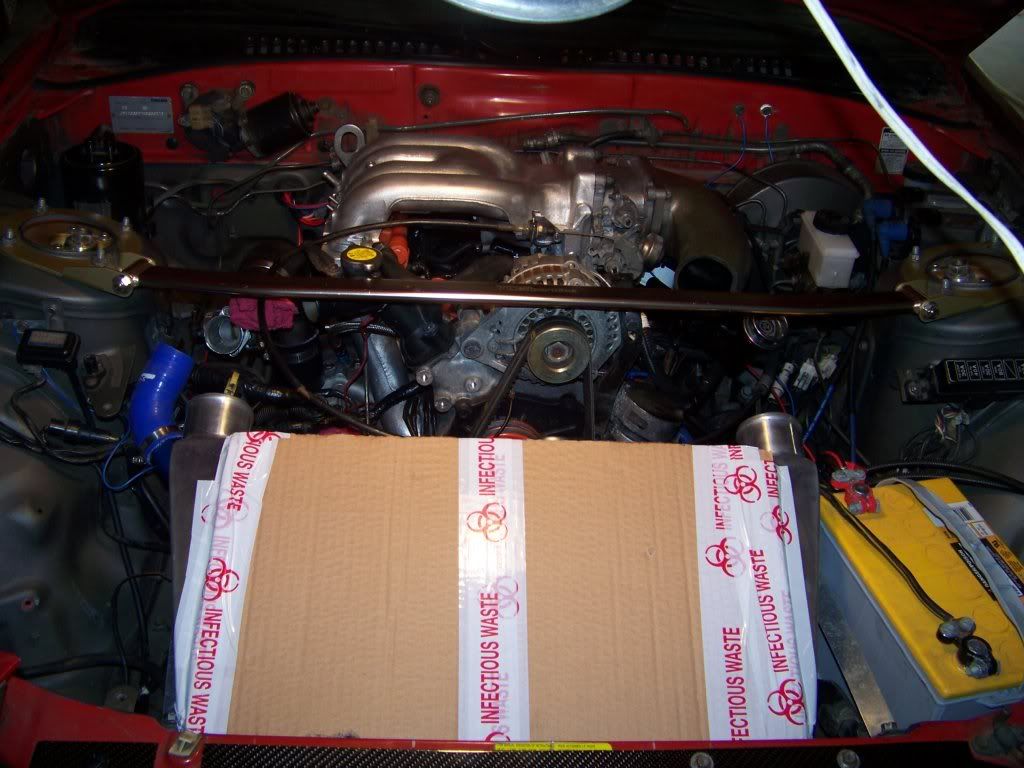
I managed to get the 3,600CFM e-fan on and the radiator into the right position to fit my VMIC. Still need some pipes to finish it off though. I also need to do some ducting/shrouding stuff to seal it up on the sides. The neat thing is this retained the the stock radiator and the oil cooler didn't have to be moved. I want to redo the braces in some thicker metal but it's in the right position and everything clears so far.


#21
Hey that's a real Intimidator, I had actually read a few threads about batteries before I picked this one based on your recommendation and I have been pleased overall. Though my car sits for such long periods of time that it has drained down a few times this past winter. Maybe there's something else going on like a voltage draw? I did the parasitic draw test and it seemed fine, I think it's just the weeks of not starting it and the sub zero temps....
#24
TTT didn't have major AIT issues when he ran his under the stock hood. He still modified his hood anyway to be something similar to the Atihun hoods to see if he could get the temps lower.
#25
this is good news then if ait's where good... that was one big worrie since i plan and am building a reliable dd 13-re gt35r set up. i currently just got ahold of an npr i/c just for this, but next thought would be water pump choices..


