divided manifolds & hotsides
 01-09-12, 06:00 PM
#1
divided manifolds & hotsides
Hey guys, here is something fun to play with:
How do you solve cross-port/runner-communications using a divided turbo setup on a 3rotor?
A) Do you join all 3 runners at the divided flange and let 'em fight it out?
B) Do you play some sort of gymnastics with the tubing to build a 3 into 2 collector?
C) Do you run join runners #1 & #2 at the left side leaving #3 for the right side of the flange?
D) Attempt to run #1 and #3 to each side of the flange and attempt to span #2 over both side?
..Anyhow, post your thoughts.. let's hash it out!
 01-10-12, 09:39 AM
#3
20b Tinkerer
iTrader: (1)
Join Date: Jan 2002
Location: TX
Posts: 240
Likes: 0
Received 0 Likes
on
0 Posts
I think your suggestion in C would be pretty close to what I'm envisioning my manifold layout to be, and also the result of the poll. Collected 3-1 pre-turbo into a divided housing.
My plan is still to have two tubes pointed at one opening in the divided housing and the third pointed at the other. I'm going to use the flapper in a quick spool valve along with a narrowed dividing bridge to direct the 3rd runner towards the other side while the valve was closed.
Similar to this.(hotlinked)

I'm planning on having the 2 runner opening be the opening closest to the base of the turbine (part with the longest blade length) to get the best torque delivered at low gas velocities. Thoughts?
My plan is still to have two tubes pointed at one opening in the divided housing and the third pointed at the other. I'm going to use the flapper in a quick spool valve along with a narrowed dividing bridge to direct the 3rd runner towards the other side while the valve was closed.
Similar to this.(hotlinked)
I'm planning on having the 2 runner opening be the opening closest to the base of the turbine (part with the longest blade length) to get the best torque delivered at low gas velocities. Thoughts?
01-11-12, 03:51 PM
#5
20b Tinkerer
iTrader: (1)
Join Date: Jan 2002
Location: TX
Posts: 240
Likes: 0
Received 0 Likes
on
0 Posts
Did you see this thread?
https://www.rx7club.com/20b-forum-95/myth-about-20b-exhaust-sleeves-963794/
The QSV is the cheapest way I know of to gain dynamic control of manifold volume. I think that tradeoff is worth the slight penalty in back pressure at low RPM when the flapper is closed. Also, I don't think the change in flow direction would be any more drastic than what the factory 20b manifold had.
That said, I still haven't built my manifold. If you've got SAE papers / technical books in mind, I'm all for refining the design before I build it.
01-11-12, 08:43 PM
#6
Did you see this thread?
https://www.rx7club.com/showthread.php?t=963794
The QSV is the cheapest way I know of to gain dynamic control of manifold volume. I think that tradeoff is worth the slight penalty in back pressure at low RPM when the flapper is closed. Also, I don't think the change in flow direction would be any more drastic than what the factory 20b manifold had.
That said, I still haven't built my manifold. If you've got SAE papers / technical books in mind, I'm all for refining the design before I build it.
I've seen the other thread and Chris's manifold was the only one I agreed with.
01-12-12, 11:58 AM
#7
20b Tinkerer
iTrader: (1)
Join Date: Jan 2002
Location: TX
Posts: 240
Likes: 0
Received 0 Likes
on
0 Posts
Not useful. That's what we're trying to work out.
I think you're misinterpreting what I'm saying, no runner is capped. All 3 runners are open to a single void before the turbo.
- In the QSV case,the volume control goes on after all 3 runners have merged. The void would be the same as Chris' collector, but the center line of the runners would be aimed at a particular opening on the divided manifold instead of the center of the void (per Chris' collector)
- In the conceptual case this drawing below is what I think the best design is, stretched it out to a straight line to simplify for discussion. You get the best of both worlds here. During low flow, you get the most exhaust delivering the greatest force on the turbo. During high flow, you restrict cross-runner communication as best as possible and do not sacrifice flow with convoluted exhaust paths. I think exact implementation of this would be difficult due to space restrictions, sealing issues on the flapper, and complexity. Hence the QSV compromise.
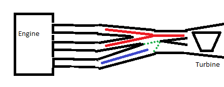
The green dotted lines are the 2 positions for the flapper, which would operate as you would expect.
- In the QSV case,the volume control goes on after all 3 runners have merged. The void would be the same as Chris' collector, but the center line of the runners would be aimed at a particular opening on the divided manifold instead of the center of the void (per Chris' collector)
- In the conceptual case this drawing below is what I think the best design is, stretched it out to a straight line to simplify for discussion. You get the best of both worlds here. During low flow, you get the most exhaust delivering the greatest force on the turbo. During high flow, you restrict cross-runner communication as best as possible and do not sacrifice flow with convoluted exhaust paths. I think exact implementation of this would be difficult due to space restrictions, sealing issues on the flapper, and complexity. Hence the QSV compromise.
The green dotted lines are the 2 positions for the flapper, which would operate as you would expect.
Trending Topics
01-12-12, 06:46 PM
#8
Not useful. That's what we're trying to work out.
I think you're misinterpreting what I'm saying, no runner is capped. All 3 runners are open to a single void before the turbo.
- In the QSV case,the volume control goes on after all 3 runners have merged. The void would be the same as Chris' collector, but the center line of the runners would be aimed at a particular opening on the divided manifold instead of the center of the void (per Chris' collector)
- In the conceptual case this drawing below is what I think the best design is, stretched it out to a straight line to simplify for discussion. You get the best of both worlds here. During low flow, you get the most exhaust delivering the greatest force on the turbo. During high flow, you restrict cross-runner communication as best as possible and do not sacrifice flow with convoluted exhaust paths. I think exact implementation of this would be difficult due to space restrictions, sealing issues on the flapper, and complexity. Hence the QSV compromise.
The green dotted lines are the 2 positions for the flapper, which would operate as you would expect.
Thanks for explaining but thats all you.
01-13-12, 06:01 PM
#9
Rotary Enthusiast
i dunno ......i wouldnt put anything in the exhaust path of a 20B ,a turbo itself is restriction enough
especially ported ,i believe these engines need to breathe
they need a shitload of exhaust flow
especially ported ,i believe these engines need to breathe
they need a shitload of exhaust flow
01-21-12, 04:05 PM
#10
Moderator
iTrader: (3)
Join Date: Mar 2001
Location: https://www2.mazda.com/en/100th/
Posts: 30,986
Received 2,688 Likes
on
1,903 Posts
about 10 years ago, we (Mr K, Mr Yamada, Mr Koseki and my self, had basically three different solutions.
basically you cannot divide 3 exhaust ports into 2 sides of a turbo.
the easy solution is an HKS T51, its just the right size turbo, undivided yes, but its simple.
the complex solution #1. run two turbos. one turbo is setup like a 2 rotor on 2 ports. the second turbo needs to be small and run off of just the one rotor. its kind of like the stock setup. just because you can't divide 3/2 didn't stop mazda....
complex solution #2. run one big divided turbo, and just don't use the 3rd rotor to run a turbine. like a rotary needs more exhaust energy... i see problems with balance
complex solution #3 run 3 turbos! plumbing is going to suck, the turbos will fight if they share a common intake. its expensive, and space is a problem....
in reality none of us tried any of these, 3 rotor and having a life don't go together well
01-21-12, 09:31 PM
#11
about 10 years ago, we (Mr K, Mr Yamada, Mr Koseki and my self, had basically three different solutions.
basically you cannot divide 3 exhaust ports into 2 sides of a turbo.
the easy solution is an HKS T51, its just the right size turbo, undivided yes, but its simple.
the complex solution #1. run two turbos. one turbo is setup like a 2 rotor on 2 ports. the second turbo needs to be small and run off of just the one rotor. its kind of like the stock setup. just because you can't divide 3/2 didn't stop mazda....
complex solution #2. run one big divided turbo, and just don't use the 3rd rotor to run a turbine. like a rotary needs more exhaust energy... i see problems with balance
complex solution #3 run 3 turbos! plumbing is going to suck, the turbos will fight if they share a common intake. its expensive, and space is a problem....
in reality none of us tried any of these, 3 rotor and having a life don't go together well
basically you cannot divide 3 exhaust ports into 2 sides of a turbo.
the easy solution is an HKS T51, its just the right size turbo, undivided yes, but its simple.
the complex solution #1. run two turbos. one turbo is setup like a 2 rotor on 2 ports. the second turbo needs to be small and run off of just the one rotor. its kind of like the stock setup. just because you can't divide 3/2 didn't stop mazda....
complex solution #2. run one big divided turbo, and just don't use the 3rd rotor to run a turbine. like a rotary needs more exhaust energy... i see problems with balance
complex solution #3 run 3 turbos! plumbing is going to suck, the turbos will fight if they share a common intake. its expensive, and space is a problem....
in reality none of us tried any of these, 3 rotor and having a life don't go together well
the thought I had was to send runner #1 to the left side of the flange, runner # to the right side of the flange then to a 1->2 (backward merge collector) for runner #2.
runner #2 would split/merge into both left & right side of the divided flange.
...that was my idea until I realized moments later - #2 runners pulses will be cut in half - they'll not travel as fast as #1 & #3 therefore #2's split pulses must cause impedance.
I'll probably end up sending #1 & 2 into the same side of the divided-flange.
01-24-12, 10:32 AM
#12
Moderator
iTrader: (3)
Join Date: Mar 2001
Location: https://www2.mazda.com/en/100th/
Posts: 30,986
Received 2,688 Likes
on
1,903 Posts
although since the engine has 120 degree firings does this still work?
01-24-12, 12:19 PM
#14
Banned. I got OWNED!!!

This is how I will be doing it.. using T4 or V-band flange, and a 60mm Tial gate:
http://www.flickr.com/photos/74953263@N07/6755985193/http://www.flickr.com/photos/74953263@N07/6755985193/ by http://www.flickr.com/people/74953263@N07/, on Flickr
http://www.flickr.com/photos/74953263@N07/6755985095/http://www.flickr.com/photos/74953263@N07/6755985095/ by http://www.flickr.com/people/74953263@N07/, on Flickr
http://www.flickr.com/photos/74953263@N07/6755985279/http://www.flickr.com/photos/74953263@N07/6755985279/ by http://www.flickr.com/people/74953263@N07/, on Flickr
http://www.flickr.com/photos/74953263@N07/6755985343/http://www.flickr.com/photos/74953263@N07/6755985343/ by http://www.flickr.com/people/74953263@N07/, on Flickr
I'll post pics of the finished manifolds later this week.
05-07-12, 05:21 PM
#15
IFO Forced Induction Slo
iTrader: (3)
Join Date: Mar 2004
Location: Houston
Posts: 1,315
Likes: 0
Received 0 Likes
on
0 Posts
Sorry for the revival, but I only saw one comment at my situation.
"If you have to run a divided turbine on a undivded manifold you need to cut the divider back .5" minimum don't knife edge it just cut it back in the shape of a U or C this will help balance flow into the housing. " - Last edited by A-Spec Tuning; 08-01-11 at 11:05 AM.
from this thread https://www.rx7club.com/showthread.php?t=963820
I already acquired my GT4202 and my turbine housing is split. My manifold is not built yet.
What are the negative effects, if any, of using a manifold that combines all three runners into a non-split T4 flange with a split turbine housing? Will the divider in the turbine melt/wear excessively?
05-15-12, 02:32 PM
#16
Senior Member
iTrader: (1)

Join Date: Sep 2001
Location: San Francisco
Posts: 321
Likes: 0
Received 0 Likes
on
0 Posts
It looks beautiful, however, I'd rather have WG opening on the inside of the radius (less interruptive to the exhaust flow), so the turbo gets better spool.
This is how I will be doing it.. using T4 or V-band flange, and a 60mm Tial gate:

20B T4 MANIFOLD - 2.0 2 by SENZA PARI #1, on Flickr
I'll post pics of the finished manifolds later this week.
20B T4 MANIFOLD - 2.0 2 by SENZA PARI #1, on Flickr
I'll post pics of the finished manifolds later this week.
05-19-12, 01:56 AM
#18
Senior Member
iTrader: (1)
Join Date: Sep 2001
Location: San Francisco
Posts: 321
Likes: 0
Received 0 Likes
on
0 Posts
Do you even have a 20B turbo? speaking from experience?? I can tell you from ACTUAL experience, unless you're running a restrictive turbo, having the WG on the other side will work.
Regardless, I'd still error on the side of more exhaust flow to the turbo...
Regardless, I'd still error on the side of more exhaust flow to the turbo...
05-28-12, 08:50 AM
#19
IFO Forced Induction Slo
iTrader: (3)
Join Date: Mar 2004
Location: Houston
Posts: 1,315
Likes: 0
Received 0 Likes
on
0 Posts
Bumping this back to the top.
Even though I've done other research in other corners of the internetz, I still dont seem to have a clear understanding or answer for my question above.
I already own a GT4202 with split turbine housing. I am considering building a manifold that will combine all three runners to a T4 flange with the center divider/bridge possibly cut out. If it is cut out, I have seen other folks on other forums explain that the divider in the turbine should be ground down about a half inch deep, and the actual split should be rounded. The split should also be in a semi-circle shape. Anyone else confirm this?
I was thinking on my own, completely going against my therapists recommendations, that instead of grinding into my turbine housings, that I could cut a thick (maybe 5/8" or 3/4") T4 flange, and grind the flange into a better shape than a blunt edge.
I hope I'm explaining this correctly. I have the idea in my head, but I'm having trouble explaining it. Anyone understand what I'm talking about?
Thanks in advance.
06-02-12, 10:24 AM
#20
Bumping this back to the top.
Even though I've done other research in other corners of the internetz, I still dont seem to have a clear understanding or answer for my question above.
I already own a GT4202 with split turbine housing. I am considering building a manifold that will combine all three runners to a T4 flange with the center divider/bridge possibly cut out. If it is cut out, I have seen other folks on other forums explain that the divider in the turbine should be ground down about a half inch deep, and the actual split should be rounded. The split should also be in a semi-circle shape. Anyone else confirm this?
I was thinking on my own, completely going against my therapists recommendations, that instead of grinding into my turbine housings, that I could cut a thick (maybe 5/8" or 3/4") T4 flange, and grind the flange into a better shape than a blunt edge.
I hope I'm explaining this correctly. I have the idea in my head, but I'm having trouble explaining it. Anyone understand what I'm talking about?
Thanks in advance.
Even though I've done other research in other corners of the internetz, I still dont seem to have a clear understanding or answer for my question above.
I already own a GT4202 with split turbine housing. I am considering building a manifold that will combine all three runners to a T4 flange with the center divider/bridge possibly cut out. If it is cut out, I have seen other folks on other forums explain that the divider in the turbine should be ground down about a half inch deep, and the actual split should be rounded. The split should also be in a semi-circle shape. Anyone else confirm this?
I was thinking on my own, completely going against my therapists recommendations, that instead of grinding into my turbine housings, that I could cut a thick (maybe 5/8" or 3/4") T4 flange, and grind the flange into a better shape than a blunt edge.
I hope I'm explaining this correctly. I have the idea in my head, but I'm having trouble explaining it. Anyone understand what I'm talking about?
Thanks in advance.
Look.. its just not going to work until we get a flange and hotside that allows for this.
Maybe we can make a "T20b" flange that has 3 outlets .vs typical 2?
..then we'll build the hotsides to have 3 inlet tracks..
problem solved.
on a serious note, the T51 flange idea.. still has its inherit problem of air speed, pressure dropping. As soon as the flowing gas hits the "collected 3 into 1" section - its going to expand and slow down - probably causing a 'traffic jam' for the rest of the exhaust pulses coming out of the engine.
so, start on the T20B hotside and I'll make the T20B flanges.. :-)
06-03-12, 11:24 AM
#21
IFO Forced Induction Slo
iTrader: (3)
Join Date: Mar 2004
Location: Houston
Posts: 1,315
Likes: 0
Received 0 Likes
on
0 Posts
Lol...the flanges are the easy part!!!
I've decided I'm going to go with a thick T4 flange and "work" the center divider/spliter to be less of a blunt edge. Hope before the next decade I will post my results.
I've decided I'm going to go with a thick T4 flange and "work" the center divider/spliter to be less of a blunt edge. Hope before the next decade I will post my results.
12-20-12, 11:45 PM
#23
Junior Member

Join Date: Dec 2012
Location: San Diego, Ca
Posts: 6
Likes: 0
Received 0 Likes
on
0 Posts
about 10 years ago, we (Mr K, Mr Yamada, Mr Koseki and my self, had basically three different solutions.
basically you cannot divide 3 exhaust ports into 2 sides of a turbo.
complex solution #3 run 3 turbos! plumbing is going to suck, the turbos will fight if they share a common intake. its expensive, and space is a problem....
in reality none of us tried any of these, 3 rotor and having a life don't go together well
If I were to build a 550-600hp 20b and want to run triples, what size turbos would be ideal for that hp range? Maybe have a little extra for a race gas tune, but I'd like to have 2 street tunes, one 500 ish, and another 600 ish.
When I searched not much came up, and trying to search for twin single aftermarket turbo 13b was near impossible because stock twins threads kept coming up.
Hang with me, I've been doing some math, so help me out in my thought process:
This thread:
https://www.rx7club.com/single-turbo...-plots-966464/
talks about some turbo calcs for a 2-rotor and while not exact are generally accepted as pretty close. I found that a 2-rotor is said to be similar to a 158.6cid motor. I assumed/calculated the following for a 20b:
237.9 cid (158.6/2 *3)
7500rpm, 90% VE
12 psi = 847.48 cfm = 58.56 lb/min
15 psi = 938.59 cfm = 64.86 lb/min
18 psi = 1031.52 cfm = 71.28 lb/min
This seems to be a little low based off of the turbos used and hp at psi boost made (from my limited knowledge and research), but I'm going to go with it because its kinda close.
I figured triples would use each rotor as its own motor so I assumed/calculated the following:
79.3cid (158.6/2)
7500rpm, 90% VE
12 psi = 281.88 cfm = 19.48 lb/min
15 psi = 312.86 cfm = 21.62 lb/min
18 psi = 343.83 cfm = 23.76 lb/min
it seems a turbo that flows 20-25 lb/min would be ideal, but up to 30-35 for a race tune and/or error in calculations.
I have used Borg Warner Turbos a lot in the diesel world and they seem to be gaining popularity in the 13b scene so I figured I'd look there first.
The S250 seem like a decent fit:
BorgWarner Turbo S200SX-50 S250 (S200) PN: 177267

I found this map, but cont confirm it's the actual BW S252, but it seems pretty close.
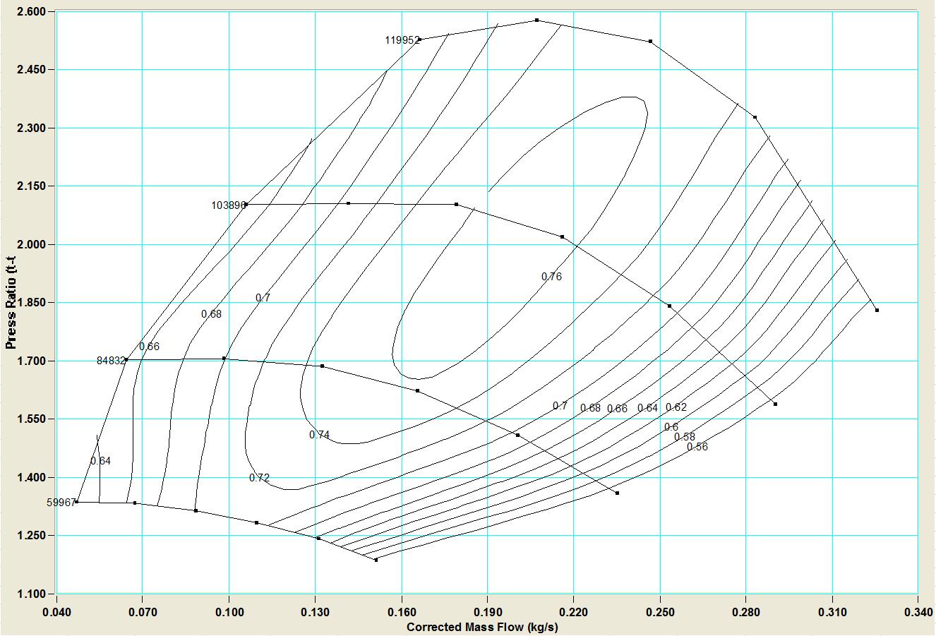
25 lb/min = 0.189 kg/s
Or how about the good ole GT28r or GT30r?
Thanks for hanging in with my ramblings!
02-10-13, 11:12 AM
#25
good luck running 3 turbos under the hood.. will be a nightmare of plumbing and a shitload of heat in a tiny engine bay compartment.
if i ever do another turbo 20b i'll stick to my divided twin scroll manifold that worked amazing on my old car. thats if i can find another 20b engine
if i ever do another turbo 20b i'll stick to my divided twin scroll manifold that worked amazing on my old car. thats if i can find another 20b engine