
1000 HP 20B Street Car Project
 09-01-04, 08:27 PM
#151
Boostless FD
Join Date: Mar 2001
Location: San Antonio, TX
Posts: 1,693
Likes: 0
Received 0 Likes
on
0 Posts
Originally Posted by Auto Illusions
Thank you for the input. As i remember removing the exhaust gaskets i believe they were thin steel and individual as you said.
I will be looking into it....Racing beat sent them to me and were supposed to be for the FD......
With so much going on with the project and work..... i am missing a few things!
Thanks for pointing that out......
I will be looking into it....Racing beat sent them to me and were supposed to be for the FD......
With so much going on with the project and work..... i am missing a few things!
Thanks for pointing that out......

 09-01-04, 10:22 PM
#152
Lives on the Forum

Originally Posted by Auto Illusions
Well, since you asked....They are FD gaskets, the rear which is a one piece gasket for the rear 2 rotors are as they come and the front (single) is 1/2 a gasket cut off also from the FD!
I dunno where you got those from (Racing Beat?), but they look totally wrong.
Even the FC3S turbo ones were smooth stainless steel - one gasket covering both exhaust ports on a 13B.
The pics look like FC3S non-turbo ones, which are perforated metal type like in your pics.
Have you ever looked inside a stock 20B plenum? Maybe i am wrong....A flow bench normally does not lie!
I don't like the stock design either.
No, I don't have the resources to build an intake manifold from scratch.
You don't want me to get into arguments about flowbenches.
Yes, they have their uses, but I find using them as the end-all argument for real-world airflow performance a little flawed.
-Ted
09-02-04, 11:01 AM
#153
working towards the goal

Join Date: Apr 2004
Location: Georgia
Posts: 402
Likes: 0
Received 0 Likes
on
0 Posts
For the time being I will be boaring out the stock intake manifold. But I will get a custom intake manifold at some point. Flow benches are not 100% accurate but can prove that one item can out flow another. You could assume that in a real world application the item the outflowed on the bench will probably still outflow on the road. Agreed??
Last edited by Drag'nGT; 09-02-04 at 11:06 AM.
09-02-04, 02:08 PM
#154
Senior Member
Thread Starter

Join Date: Aug 2003
Location: Moon Twp. Pennsylvania
Posts: 703
Likes: 0
Received 0 Likes
on
0 Posts
I got some real numbers....
Flow testing a ported stock mani which has been extrude honed as well compared to the full sheet metal intake i have....
There was a difference of 70 to 80 cfm gain per runner..
The new custom intake flows 400 cfm on the large tubes and 198 cfm on the small ones.
The difference between the runners (big and small compared seperately) was 5cfm or less! That is a real close match but well see what happens in a real world working sittuation.
Last edited by Auto Illusions; 09-02-04 at 02:10 PM.
09-02-04, 08:00 PM
#155
Lives on the Forum
Originally Posted by Drag'nGT
You could assume that in a real world application the item the outflowed on the bench will probably still outflow on the road. Agreed??
My problems with flow benches is that they are typically measure at a static "vacuum" rate.
Or am I assuming too much here?
According to fluid dynamics...
There is a difference between push and pull fluid dynamics.
I believe most flow benches are vacuum after the manifold; this assumes pull fluid dynamics.
A forced induction engine is a combination of push and pull fluid dyamics.
Now, this might be insignificant, but I'm more worried about the dynamic changes in airflow.
If airflow through the manifold was set at or very close to the flow bench parameters, then the results would be surely applicable.
A (rotary) engine revving from 500RPM to 8000RPM and then adding on the variable of forced induction anywhere from vacuum to 20psi+ make for some very interesting results, and I wouldn't trust a flow bench running static vacuum to be a true test of this real-world dynamics?
Don't get me wrong...testing several manifold on the flow bench does allow for reasonable comparison of the results.
If manifold A outflows manifold B on the flow bench, I'm sure it does too on the engine itself.
What I would be worried about is balanced airflow through all 3 rotors.
Slight deviations in each rotor airflow would change AFR's in the combustion.
We don't need to go into what happens when the airflow differntials are significant.

With a 13B, splitting 1 into 2 is not as bad as splitting 1 into 3 for a 20B.

-Ted
09-02-04, 08:32 PM
#156
Senior Member
Thread Starter
Join Date: Aug 2003
Location: Moon Twp. Pennsylvania
Posts: 703
Likes: 0
Received 0 Likes
on
0 Posts
That was pretty much what i was told...
I agree with all that you had said.....
The largest problem with the stock mani is it is a little restrictive for High HP applications since it was not designed for it.........
Also after building a high Hp 20B, i am told from other peoples experience that when you lean out a motor causing it to break, it is usually the center rotor which was getting to much air!
I will let all know how it works out once running.....
09-03-04, 03:06 AM
#157
Lives on the Forum
Originally Posted by Auto Illusions
The largest problem with the stock mani is it is a little restrictive for High HP applications since it was not designed for it.........
We're trying to only shoot for 600hp to 700hp.
I hope the stock manifold is adequate.
Also after building a high Hp 20B, i am told from other peoples experience that when you lean out a motor causing it to break, it is usually the center rotor which was getting to much air!
I will let all know how it works out once running.....
I will let all know how it works out once running.....
If you stare at the inlet from the throttle body to the runners in the intake manifold, the center rotors looks like it'll get the majority of the direct airflow.
As a band-aid, most stand-alones can handle individual adjustments on fuel injectors, but it's still a band-aid.
Keep us updated - I'm curious on your project also!
-Ted
09-03-04, 07:48 AM
#158
Senior Member
Join Date: Feb 2001
Location: Charlotte, N.C.
Posts: 445
Likes: 0
Received 0 Likes
on
0 Posts
A good standalone should allow the user to be able to tune each rotor/cylinder of an engine individually anyways. I grew up tuning 2 stroke engines from Snowmobiles, and one thing I learned was that even if you had a 3 cylinder engine, you treated each individual cylinder as if it were its own seperate engine when dialing in the carbeurators. It wasn't uncommon to see one cylinder be richer/leaner than another cylinder by 2-3 jet sizes
09-03-04, 10:49 AM
#159
Senior Member
Thread Starter
Join Date: Aug 2003
Location: Moon Twp. Pennsylvania
Posts: 703
Likes: 0
Received 0 Likes
on
0 Posts
I am going to be running a motec 800 ECU which can tune each rotor seperately.....
I am considering what would be best to use as a tunning tool, either an EGT or Wideband O2 in each exhast runner.
This would be used for fine tunning each of the output after a base map has been established!
Any suggestions on this?
The car will have a built in wide band with a 2" lcd in car display to monitor it constantly, i am still considering installing EGT's in the car....
Last edited by Auto Illusions; 09-03-04 at 10:51 AM.
09-03-04, 01:44 PM
#161
Senior Member
Thread Starter
Join Date: Aug 2003
Location: Moon Twp. Pennsylvania
Posts: 703
Likes: 0
Received 0 Likes
on
0 Posts
That is for sure....I don't think it is even necessary to tune individually unless you are trying to push it to the limit...
Most of the time you would tune with some cussion and each rotor would be so close to one another in tunning that it is not necessary.
If you have to correct for fuel more than a couple of % between the rotors then you have a problem that needs to be addressed in a different way than fuel correction!
09-03-04, 03:53 PM
#162
working towards the goal
Join Date: Apr 2004
Location: Georgia
Posts: 402
Likes: 0
Received 0 Likes
on
0 Posts
Well. I have plans to run 600-700whp (as most of us do) but not on a constant basis. But when I do turn the boost up I'm gonna need a good high flow manifold. I'm gonna be stressing the motor enough running that kind of power. I don't want the car to feel like it's breathing through a straw.
09-03-04, 07:51 PM
#163

Mine wasn't haveing any problems with 587rwhp. I have a stock manifold with q45 90mm tb. Not quite in the 600 range but i'll be shooting for 650ish fairly soon and I don't see this setup being any trouble pushing it out.
-Destin
-Destin
09-05-04, 09:52 PM
#165
Full Member

Join Date: Jan 2004
Location: Orlando
Posts: 229
Likes: 0
Received 0 Likes
on
0 Posts
I'm really interested in the whole TB and manifold concept behind the 20B. I'm curious because my friends 20B with ported manifolds, large port job and fully built, with a thumper series turbo... he put over 800 rwhp at 25 psi on C16. Now I'm going to start a 20B and my set up is fairly similiar to yours. The main difference is the intake manifold set up, I was planning on just getting the manifolds ported out nicely. But, now you guys have me thinking. Where actually could I have custom manifold built, by someone knowledgable and reputable? And how much do they run for? Which may I add that I realize when building a hopeful 900rwhp rotary, money should not be an issue. However I'm not wealthy, my mods soley rely on my income, and I'm going to college... so I'd like to save every penny I can if possible.
Thanks,
Alex
Thanks,
Alex
09-07-04, 10:42 AM
#166
Senior Member
Thread Starter
Join Date: Aug 2003
Location: Moon Twp. Pennsylvania
Posts: 703
Likes: 0
Received 0 Likes
on
0 Posts
I have been PMed a few times with the same question as well as i can see a little interest here......
The alum mani like this one would cost around $4000
If any one is interested, i might be building another one!
The alum mani like this one would cost around $4000
If any one is interested, i might be building another one!
09-08-04, 10:35 AM
#167
working towards the goal
Join Date: Apr 2004
Location: Georgia
Posts: 402
Likes: 0
Received 0 Likes
on
0 Posts
Woah! $4000??? I guess I'll stick with a boared out stock mani and a good ecu controlling every rotor AFM.
I take it no one overseas made an aftermarket intake manifold?
I take it no one overseas made an aftermarket intake manifold?
09-08-04, 12:26 PM
#168
You can get one from Hogans for $3000. I think that was the price they quoted me awhile back.
http://www.hogansracingmanifolds.com/
They have an excellant reputation btw.
http://www.hogansracingmanifolds.com/
They have an excellant reputation btw.
Last edited by RX-Heven; 09-08-04 at 12:40 PM.

 09-08-04, 12:44 PM
#170
Senior Member
Thread Starter
Join Date: Aug 2003
Location: Moon Twp. Pennsylvania
Posts: 703
Likes: 0
Received 0 Likes
on
0 Posts
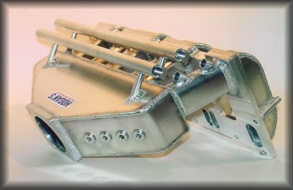
Wow, that looks similar.... I guess i have some questions to ask!!!
The fuel rails and injectors are on the side for hood clearance...
I wanted them under the plenum but i was told they would not fit!
Heat shields will be installed as well.
The fuel rails and injectors are on the side for hood clearance...
I wanted them under the plenum but i was told they would not fit!
Heat shields will be installed as well.
09-08-04, 05:44 PM
#171
Junior Member

Join Date: Sep 2004
Location: Sweden
Posts: 13
Likes: 0
Received 0 Likes
on
0 Posts
I'm not an expert in flow tech, but i have picked up a few things at my work. I've been working with some windtunnel models in the aircraft industry air intakes and stuff.. I wonder if this inlet really is that good? Looks not that smooth like it should be? And i wonder how good it is to use one throttle body in the center?
maybe 2 or 3 smaller TB:s on differen't runners for better distribution between the rotor chambers? Does it have to be that fancy? Is it possible to mod the original inletmanifold or make a new one with larger runner or a better plenum?
maybe i'm totally wrong but i don't like what i see
I've done some testing with differen't inlets on 4 cylinder engines..
To mension one test i did was with a single weber carb placed in the center..
didn't work good at all.. and the engine started to drink lot's of fuel too
Originally Posted by RX-Heven
You can get one from Hogans for $3000. I think that was the price they quoted me awhile back.
http://www.hogansracingmanifolds.com/
They have an excellant reputation btw.
http://www.hogansracingmanifolds.com/
They have an excellant reputation btw.
09-08-04, 06:52 PM
#172
Senior Member
Thread Starter
Join Date: Aug 2003
Location: Moon Twp. Pennsylvania
Posts: 703
Likes: 0
Received 0 Likes
on
0 Posts
I was under the impression that the intake was one of a kind.....
I have been mislead to believe that he was making the intake when it actually come from Hogans!
For this reason i will be selling the entire assembly in which i had full polished as you can see... I paid $3900 for the intake with the fuel rails and around $300 for full polish plus an additional $175 to port match the upper plenum to the lower intake manifold as well as the lower to the stock gasket.....
My loss but i will sell the complete Intake with fuel rails and full polish for $3500 and another $280 for the throttle body...
I talked with Hogans today and they are asking $3200 for the intake and another $200 for the fuel rails with about a 4-6 week wait.
I am now making my own from scratch, something i did not have the time to do before but am now willing to do in order to have a one of a kind custom intake....
I will post pics once it has been started....
Last edited by Auto Illusions; 09-08-04 at 06:57 PM.
09-08-04, 11:37 PM
#174
Rebreaking things
Join Date: Jun 2001
Location: 1 foot in Boston 1 in NJ
Posts: 2,586
Likes: 0
Received 0 Likes
on
0 Posts
Originally Posted by Auto Illusions
I was under the impression that the intake was one of a kind.....
I have been mislead to believe that he was making the intake when it actually come from Hogans!
For this reason i will be selling the entire assembly in which i had full polished as you can see... I paid $3900 for the intake with the fuel rails and around $300 for full polish plus an additional $175 to port match the upper plenum to the lower intake manifold as well as the lower to the stock gasket.....
My loss but i will sell the complete Intake with fuel rails and full polish for $3500 and another $280 for the throttle body...
I talked with Hogans today and they are asking $3200 for the intake and another $200 for the fuel rails with about a 4-6 week wait.
I am now making my own from scratch, something i did not have the time to do before but am now willing to do in order to have a one of a kind custom intake....
I will post pics once it has been started....
I have been mislead to believe that he was making the intake when it actually come from Hogans!
For this reason i will be selling the entire assembly in which i had full polished as you can see... I paid $3900 for the intake with the fuel rails and around $300 for full polish plus an additional $175 to port match the upper plenum to the lower intake manifold as well as the lower to the stock gasket.....
My loss but i will sell the complete Intake with fuel rails and full polish for $3500 and another $280 for the throttle body...
I talked with Hogans today and they are asking $3200 for the intake and another $200 for the fuel rails with about a 4-6 week wait.
I am now making my own from scratch, something i did not have the time to do before but am now willing to do in order to have a one of a kind custom intake....
I will post pics once it has been started....
09-08-04, 11:49 PM
#175
Senior Member
Join Date: Jul 2002
Location: Richland Wa.
Posts: 615
Likes: 0
Received 0 Likes
on
0 Posts
I would say that you deffinatly have been strait up lied to. I would appreciate you sharing who you were dealing with so that none of us get taken as well. I have worked in the manufacturing industry for a long time and find it pretty hard to beleive that this is not a hogan unit. Although there are some very minor differences between yours and the hogan picture most likely the hogan picture was one of there prototypes or earlier designs.
Anyway my thoughts on the design is that even though it flows more cfm than the stock manifold, it seems to me that that air would be very turbulant due to the sqare corners of the runners and relitive sharpness of the bends. This would not be ideal for creating velocity into the engine. I always find it helpful to remember that air is a liquid and has weight. Try to imagine water trying to flow through that manifold at a high rate of speed, then imagine something with smoother bending runners with a more round shape and smoother transition to the accual port shape in the motor. ZoDDy should know what air looks like trying to make a sharp courner at high speed.
Justin