GSL-SE TPS Test Tool
 02-03-08, 09:14 PM
#1
No distributor? No thanks
Thread Starter
iTrader: (6)
Join Date: Oct 2003
Location: Outskirts of Road Atlanta
Posts: 3,438
Likes: 0
Received 6 Likes
on
4 Posts
GSL-SE TPS Test Tool
I've got a pair of LED's that have built-in resistors, and I'm looking to make one test box for TPS and code-reading. I've got my wires made, but it doesn't seem to work the way I'd expect.
This thread - https://www.rx7club.com/1st-gen-archive-71/electrical-gsl-se-tps-adjustment-dummies-142695/ - no longer has pictures. I've got a red LED with the hot leg going to the right 'eye' of the test plug (left eye of my homemade harness) and the ground leg goes to the spade at the bottom. My green LED has its hot leg on the bottom leg and its ground is in the left 'eye' on the car. The problem is that I can get the green LED to light up, but not the red one.
I hear four different clicks, like a relay throwing, as I go from fully extended TPS to fully retracted. The first two don't have any impact on my lights. At the third click, my green light comes on and on the fourth it goes out. I've gone through the FSM and other writeups and it looks like I've got it wired correctly.
Any idea why my test light isn't lighting up on the low end of the TPS travel? I've used a pick to pop the pins out of my plug so I can replace the green LED with the red one. When I do, the red one lights up so I know it's good. I know I should warm the car up first, but that's not really going to affect the TPS, and the car's really loud and really stinky, so I'm trying to avoid having to run it just for a test.
 02-03-08, 09:28 PM
#3
Senior Member
Go a quarter or half turn past the clicking. I used voltmeters to dial my TPS in today. The clicking threw up mixed results in regards voltage, adding a 1/4 turn ensured it was set correctly.
02-05-08, 10:37 AM
#4
No distributor? No thanks
Thread Starter
iTrader: (6)
Join Date: Oct 2003
Location: Outskirts of Road Atlanta
Posts: 3,438
Likes: 0
Received 6 Likes
on
4 Posts
Does the TPS respond any differently on a cold engine than on a hot one? How many turns of adjustment are there between two lights and one?
I've gone back to using voltmeters, and I still can't get the first light to respond.
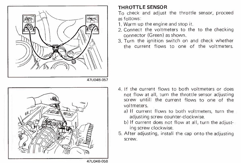
I really don't think I have it wired backwards from the FSM, as it shows one voltmeter going from the left eye (low) to the mouth (high). The other voltmeter goes from the mouth (low) to the right eye (high).
I found some very good info here. http://nellump.net/peri/epi/firstGen...gslseIdle.html
I've gone back to using voltmeters, and I still can't get the first light to respond.
I really don't think I have it wired backwards from the FSM, as it shows one voltmeter going from the left eye (low) to the mouth (high). The other voltmeter goes from the mouth (low) to the right eye (high).
I found some very good info here. http://nellump.net/peri/epi/firstGen...gslseIdle.html
02-05-08, 11:01 AM
#5
The voltmeters should work. You do have the polarity wrong on that LED, though. The 'mouth' is what is contantly powered (connect red end of LED). Each 'eye' actually connects back to the ECU to the terminals that control the vent/vac solenoids (the two silver/black cylindrical ones closest to the firewall). When the ECU pulls one of those terminals to ground (turns on corresponding vent or vac solenoid), it lights up that particular test light. When you are adjusting the TPS, you are controlling the input to the ECU which then controls the vent/vac solenoids. When one light is on, you are setting the vent solenoid to be 'ON' and the vac solenoid to be 'OFF'. So you want both red wires in the 'mouth', black wire to each 'eye'.
It is best to do this with the engine warm. You can do it cold, but may not be an accurate adjustment after the engine is warm. Best to follow the book. The clicks that you hear while adjusting are from the vent/vac solenoids switching between 'ON' and 'OFF'.
As you go between 0 lights and 2 lights, I would say there is about 1 turn or so of the screw. There is a range of adjustment (maybe a half turn or so) where just the 1 light should be on. You go from where it just goes from 0 lights to 1 light (note position) and then keep turning until you get 2 lights (note position), then turn back half-way between the 2 positions.
Trust me on the polarity. I know what I'm talking about.
Good luck.
Kent
 02-05-08, 11:41 AM
#7
No distributor? No thanks
Thread Starter
iTrader: (6)
Join Date: Oct 2003
Location: Outskirts of Road Atlanta
Posts: 3,438
Likes: 0
Received 6 Likes
on
4 Posts
Gotcha. Well, the good news is that I'm sick at home today, but I'm sure I can find some time to sort this guy out. I suppose that I just took the illustration in the FSM too seriously. Thanks guys.
Trending Topics
02-05-08, 11:52 AM
#8
No distributor? No thanks
Thread Starter
iTrader: (6)
Join Date: Oct 2003
Location: Outskirts of Road Atlanta
Posts: 3,438
Likes: 0
Received 6 Likes
on
4 Posts
Kent, do you know which leg goes high first? I only ask because I want to wire it up so my red light is out and green light is lit when everything's right.
02-05-08, 12:44 PM
#9
Yep. You should have the following:
- BW wire in the 'mouth'
- WG wire in one 'eye'
- WB wire in the other 'eye'
The WB is for the vent solenoid (goes to terminal h on ECU) and should be the one that is 'ON' when doing the test. So you'll want your green LED to go between the WB and BW terminals. The red going between the WG and BW terminals.

Thread
Thread Starter
Forum
Replies
Last Post
ZaqAtaq
New Member RX-7 Technical
2
09-05-15 08:57 PM