Cold/Ram air box fabrication for my ITB


 06-11-09, 11:25 PM
#2
We'll finally got a bit more time on my hands right now to explain things.
As the title states, its a cold/ram air box for my ITB's. Since is a DCOE type manifold that it sits on, its getting all the air from ontop of the engine bay right now which is pretty hot.
All the white parts are what's going to get bolted hence the 1/8" thickness for a bit more beefed up part that won't flex as easily. All the red parts are what make up all the sheet metal that is the main contrustion of the box. The green part is just a new throttle cable holder as oppose to the mickey mouse one that I made a while back but just doesn't look good. (All parts will be laser cut for best accuracy)
The whole intake will be 3 pieces once all welded up:
1) The plate that bolts inbetween the ITB, and the air horns,
2) The center section that covers pretty much just the air horns,
3) The end section where the 4" cold/ram air tube will be bolted up to.
Now I could of made the whole thing out of only 2 pieces, but I wanted to be able to play around with different plenum volumes so I figured this is going to most likely be the easiest way to do it.
On the end section there, there will be about a 1" long 4" wide tube welded on there to bolt on flexible tubing. Also the angle that the opening is set at is a bit more biased to the rear rotor (due to the fact that the front will already have the shortest distance and this should balance it out a bit.)
Once I have all the pieces welded up, they will be sent out to get nickel coated. I was going to do zinc at first but after talking with the owner of the plating place, its not going to with stand too much abuse (bolting and unbolting) and will rust easier than nickel. I might also get them to polish up the whole piece but we'll see about that because I might just buy of DEI's reflect-a-gold tape and put it on there to provide better heat reflection.

I was hoping to skip all those step and just do it out of stainless, but after finding out its going to cost me about 200$ more for the stainless, I figured I'd look at other options. The plating will only be about 40-50$ (including polishing). The laser cut parts will be about 150$, plus another 50$ or so for the tape. About a 250$ manifold. Not the cheapest, but should be effective.
As the title states, its a cold/ram air box for my ITB's. Since is a DCOE type manifold that it sits on, its getting all the air from ontop of the engine bay right now which is pretty hot.
All the white parts are what's going to get bolted hence the 1/8" thickness for a bit more beefed up part that won't flex as easily. All the red parts are what make up all the sheet metal that is the main contrustion of the box. The green part is just a new throttle cable holder as oppose to the mickey mouse one that I made a while back but just doesn't look good. (All parts will be laser cut for best accuracy)
The whole intake will be 3 pieces once all welded up:
1) The plate that bolts inbetween the ITB, and the air horns,
2) The center section that covers pretty much just the air horns,
3) The end section where the 4" cold/ram air tube will be bolted up to.
Now I could of made the whole thing out of only 2 pieces, but I wanted to be able to play around with different plenum volumes so I figured this is going to most likely be the easiest way to do it.
On the end section there, there will be about a 1" long 4" wide tube welded on there to bolt on flexible tubing. Also the angle that the opening is set at is a bit more biased to the rear rotor (due to the fact that the front will already have the shortest distance and this should balance it out a bit.)
Once I have all the pieces welded up, they will be sent out to get nickel coated. I was going to do zinc at first but after talking with the owner of the plating place, its not going to with stand too much abuse (bolting and unbolting) and will rust easier than nickel. I might also get them to polish up the whole piece but we'll see about that because I might just buy of DEI's reflect-a-gold tape and put it on there to provide better heat reflection.
I was hoping to skip all those step and just do it out of stainless, but after finding out its going to cost me about 200$ more for the stainless, I figured I'd look at other options. The plating will only be about 40-50$ (including polishing). The laser cut parts will be about 150$, plus another 50$ or so for the tape. About a 250$ manifold. Not the cheapest, but should be effective.
06-12-09, 07:19 AM
#3

If you shoot me a dxf of the CAD drawing I can get the laser cut for probably 1/3 that cost.
.01MM is to tight a tolerance for a welded construction. You may want to look at opening that up a bit. You are basically asking them to hold .0003", the 4th decimal is normally a tolerance reserved for precision grinding.
.01MM is to tight a tolerance for a welded construction. You may want to look at opening that up a bit. You are basically asking them to hold .0003", the 4th decimal is normally a tolerance reserved for precision grinding.
06-12-09, 10:38 AM
#4
If you shoot me a dxf of the CAD drawing I can get the laser cut for probably 1/3 that cost.
.01MM is to tight a tolerance for a welded construction. You may want to look at opening that up a bit. You are basically asking them to hold .0003", the 4th decimal is normally a tolerance reserved for precision grinding.
.01MM is to tight a tolerance for a welded construction. You may want to look at opening that up a bit. You are basically asking them to hold .0003", the 4th decimal is normally a tolerance reserved for precision grinding.
 ... I wish I knew you did this stuff before hand. I just tried to call up to see if they had done up my order or not to cancel it perhaps. But ofcourse the one time you call up next day to see if you're parts are done they're actually done and not waiting a week. I'll definatly tag you for the next projects that I need done. (Believe me there will be more
  )
)As for the tolerances, I think that I actually meant to write .01" not mm. Oh well, can't go wrong with more accuracy. Out of curiosity though, do you charge more for getting something cut within closer tolerances?
06-12-09, 10:49 AM
#5
No problem. Let me know on anything else. I have access to or connections for just about any MFG needs.
Yes, the tighter the tolerance chances are the more the cost. This is due to a number of factors. Example would be a 4th decimal place tolerance. To hold that tolerance would change the machine the part can be made on, more than like to a machine that is newer or cost more. Another would be due to multiple pieces being made in order to ensure you have the required number of pieces that meet the tolerance. These are pieces that you, the customer, never actually see but you certainly pay for them.
Machined parts is where you want tolerance. Lasers cut very close to begin with and 9/10 times the laser parts are then to be welded. Any welded construction will have a 2nd decimal place tolerance. You may have holes or features within the welded construction that are held tighter but not the overall assembly.
-billy
06-12-09, 01:26 PM
#6
Moderator
iTrader: (3)
Join Date: Mar 2001
Location: https://www2.mazda.com/en/100th/
Posts: 30,989
Received 2,688 Likes
on
1,903 Posts
yep welding isnt very precise, the heat moves everything around a lot...
making the PP intake was kind of an adventure...
making the PP intake was kind of an adventure...
06-12-09, 02:19 PM
#7
Well went to pick up the parts today and figured out why it was about 2.54 times the price it was suppose to be. All my measurement were in cm, but thanks to autocad, when you convert to inches for their machines, it keeps the units the same as oppose to scaling it down using the old measurement. All the guys were out on lunch, except for one, and he's like if I take you back there will you know which one they are? I was like sure, so looking around (trying to find small pieces) i look on the cutter table to see pieces what looks pretty much like my pieces but in a bigger scale. When I go back, I'll see if I can make a deal to buy those pieces and just tack them up to show how big the thing is lol.
I'll be getting a new price quote (which should be around 1/3 the price now), and things should be done for monday.
Billy, thanks for the service offering. I'm still going to take you up on that supercharger project as I told you before, but I just need to get a few more things figured out first, and a bit more money saved up for it.
J9fd3s, Did you make your intake out of aluminum? Aluminum is alot harder to get precise with, but with most other things its actually not that bad aslong as you either tack or jig your pieces up properly, and as you're welding don't let the piece over heat too much in one area. Move around a much as possible. I've welded up a fulll chassis, and making all the part seperatly using the cad files only, everything went on with extremely tight tolerances.
Trending Topics
06-13-09, 12:56 AM
#8
Well, my new parts are supposebly ready for pickup and new cost is about 65$ Much better on the pocket . I'm going to see if they're open tomorrow or not, if not it won't be till monday for the pictures. If i get it soon enought, I might be able to even get it welded that same day, and then off to the plating place next day. Then if all goes well I can hopefully have it ready for the 20th for another one of my races to a new track (well new to me).
I'll take pictures of everything, I promise
. I'm going to see if they're open tomorrow or not, if not it won't be till monday for the pictures. If i get it soon enought, I might be able to even get it welded that same day, and then off to the plating place next day. Then if all goes well I can hopefully have it ready for the 20th for another one of my races to a new track (well new to me). I'll take pictures of everything, I promise
06-13-09, 05:48 AM
#9
Lives on the Forum
My understanding is that the biggest problem with designing a proper ram air system is getting the high pressure air without creating additional turbulance. You could potentially end up with a system that starved one of the rotors, and it could even happen only at certain speeds...
Best of luck with your project. Hopefully it will work well for you.
.
Best of luck with your project. Hopefully it will work well for you.
.
06-13-09, 10:51 AM
#10
Moderator
iTrader: (3)
Join Date: Mar 2001
Location: https://www2.mazda.com/en/100th/
Posts: 30,989
Received 2,688 Likes
on
1,903 Posts
J9fd3s, Did you make your intake out of aluminum? Aluminum is alot harder to get precise with, but with most other things its actually not that bad aslong as you either tack or jig your pieces up properly, and as you're welding don't let the piece over heat too much in one area. Move around a much as possible. I've welded up a fulll chassis, and making all the part seperatly using the cad files only, everything went on with extremely tight tolerances.
so then we had to put the car on the trailer, and haul it up to our fab guy, then we went for pho...
your airbox, kinda sounds like my wheel spacer deal, thats another story though
06-13-09, 11:06 AM
#12
Moderator
iTrader: (3)
Join Date: Mar 2001
Location: https://www2.mazda.com/en/100th/
Posts: 30,989
Received 2,688 Likes
on
1,903 Posts
06-13-09, 11:11 AM
#13
Moderator
iTrader: (3)
Join Date: Mar 2001
Location: https://www2.mazda.com/en/100th/
Posts: 30,989
Received 2,688 Likes
on
1,903 Posts
My understanding is that the biggest problem with designing a proper ram air system is getting the high pressure air without creating additional turbulance. You could potentially end up with a system that starved one of the rotors, and it could even happen only at certain speeds...
Best of luck with your project. Hopefully it will work well for you.
.
Best of luck with your project. Hopefully it will work well for you.
.
he said the headlight intake worked up until a certain speed, then it went from pressure to vacuum, so over xmph it wasn't forcing air in, it was sucking air out, very weird....
the GTU dave kent bumper (the one with the cassette opening) had the intake right in the big cassette part
http://alex62.typepad.com/.shared/im...zed/rude82.jpg
http://alex62.typepad.com/.shared/im...ed/varde82.jpg
actually thats a nice setup!
06-13-09, 04:02 PM
#15
Ya i wish I could do my air box quite a bit bigger, but I have to work within the space that I have also. My biggest problem right now is that oil filler tube. Once I get done with that, I'll be making it bigger and hopefully push the air directly from the center. But also to accomodate for the smaller box, I'm going 4" tubing which is massive, but should add quite a bit more volume to the intake
06-14-09, 01:33 PM
#17
ya thats why I said "once I get done with that". I just got a second one yesterday to still drive my car while I'm working on it. But I think before I cut that out, I should probably switch to the front mount oil cooler. The Beehive is another thing in the way and is probably getting more heat ontop of the engine bay and would heat soak the intake manifold.
06-15-09, 03:16 PM
#18
Well the parts are in. You can tell that things are designed and cut properly when you can assembled it and everything stays in its place. I'll have pictures of it welded up tomorrow most likely, but here's the thing in pieces now. Also I order 15' of the 1.5" reflect a gold tape stuff.
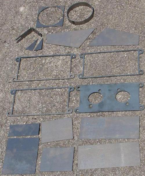
. You can tell that things are designed and cut properly when you can assembled it and everything stays in its place. I'll have pictures of it welded up tomorrow most likely, but here's the thing in pieces now. Also I order 15' of the 1.5" reflect a gold tape stuff.
06-15-09, 03:58 PM
#19
Registered shy guy
iTrader: (1)
Join Date: Jul 2007
Location: tewksbury, ma
Posts: 1,436
Likes: 0
Received 0 Likes
on
0 Posts
iam a welder by trade. you can hold .005 inches with practice on steel,and stainless after you've done it for awhile. the trick is know if you using the right amount of heat and how much your welds shrink. before we cut parts for jobs we need to know who's going to weld it. some parts are cut .020 bigger for one welder and others have them cut .010 bigger.
are you going to be tig welding this or mig.
are you going to be tig welding this or mig.
06-16-09, 12:23 AM
#20
iam a welder by trade. you can hold .005 inches with practice on steel,and stainless after you've done it for awhile. the trick is know if you using the right amount of heat and how much your welds shrink. before we cut parts for jobs we need to know who's going to weld it. some parts are cut .020 bigger for one welder and others have them cut .010 bigger.
are you going to be tig welding this or mig.
are you going to be tig welding this or mig.
Its funny how my tig welding is alot better than my Mig. Out of everything I think that mig is my least favorite process, i even prefer stick welding over it lol. I've gotten pretty good at handling small parts and thin edges to weld on. This should a breeze. I just hope that it will work out good when I put it on the car.
06-16-09, 05:09 AM
#22
Registered shy guy
iTrader: (1)
Join Date: Jul 2007
Location: tewksbury, ma
Posts: 1,436
Likes: 0
Received 0 Likes
on
0 Posts
at my work alot of the job we have to do is plus/minus .005 inch. earlier some one said it cant be done. but we do it every day at my work.
try welding 2 razor blades together sharp edge to sharp edge as a corner joint. thats a pain in the *** to do but once your able to do that you'll have a lot more control over you arc.
i know how you feel about mig id rather do wipe rod with arc then mig weld.
try welding 2 razor blades together sharp edge to sharp edge as a corner joint. thats a pain in the *** to do but once your able to do that you'll have a lot more control over you arc.
i know how you feel about mig id rather do wipe rod with arc then mig weld.
06-17-09, 01:13 AM
#23
Well looks like the first prototype fails!!! I'm really not liking that racing beat intake manifold. Why couldn't they just angle it upwards a bit? I'm hitting the engine a bit  those aluminum tabs ontop of the housings are in the way.
I'm going to try taking out my spacer for my ITB's to maybe clear that little area, but I'm not holding my hopes too high yet. I'll get pictures of it tomorrow. Atleast I did waste the money to get coated or waste the tape on it yet. If that doesn't work, I might be doing something like this but I don't know how on earth you'd get to the bolts. I can only get an open wrench on there and even a stubby one wouldn't fit in there I would assume.

those aluminum tabs ontop of the housings are in the way.I'm going to try taking out my spacer for my ITB's to maybe clear that little area, but I'm not holding my hopes too high yet. I'll get pictures of it tomorrow. Atleast I did waste the money to get coated or waste the tape on it yet. If that doesn't work, I might be doing something like this but I don't know how on earth you'd get to the bolts. I can only get an open wrench on there and even a stubby one wouldn't fit in there I would assume.
06-17-09, 09:54 AM
#24
I found myself wondering why you didn't design the box sections to be bent on a brake and then welded only at the meeting corner seams, rather than using all-welded seams & individual parts? Would eliminate half the welds, and be just slightly lighter, too.
A socket set with built-in flex joints would likely be your friend, there. I have one I use for only one job; it lets me get the thermal reactor on and off the keg without having to remove the intake manifold.
You could also consider putting an access plate on the far side of the box.
I might be doing something like this but I don't know how on earth you'd get to the bolts. I can only get an open wrench on there and even a stubby one wouldn't fit in there I would assume.
You could also consider putting an access plate on the far side of the box.
06-17-09, 10:05 AM
#25
I found myself wondering why you didn't design the box sections to be bent on a brake and then welded only at the meeting corner seams, rather than using all-welded seams & individual parts? Would eliminate half the welds, and be just slightly lighter, too.
A socket set with built-in flex joints would likely be your friend, there. I have one I use for only one job; it lets me get the thermal reactor on and off the keg without having to remove the intake manifold.
You could also consider putting an access plate on the far side of the box.
A socket set with built-in flex joints would likely be your friend, there. I have one I use for only one job; it lets me get the thermal reactor on and off the keg without having to remove the intake manifold.
You could also consider putting an access plate on the far side of the box.
It didn't make a difference weight wise because I actually just fusion welded the edges. If I do another one I might see if the laser place has one that they can do it for me. But it wouldn't be a big problem. As for the socket with a built in joint, I can't fit a socket on there, the gap between the air horn and the bolt is too small. I might try out one of the crowfoot wrenches though.
What do you mean by putting an access plate on the far side though?