
Megasquirt just another way to megasquirt your FD
 08-29-13, 09:04 PM
#1
Junior Member
Thread Starter
Join Date: May 2012
Location: russia, vladivostok
Posts: 46
Likes: 0
Received 0 Likes
on
0 Posts
just another way to megasquirt your FD
Hello everybody.
I'm using ms-2 on my FD more than year. Now it's running parallel with stock ecu. stock one controls solenoids, seq. boost, OMP, fan & AC. ms-2 controls idle, ignition & fuel.
So i'm plain to go standalone with ms-3.
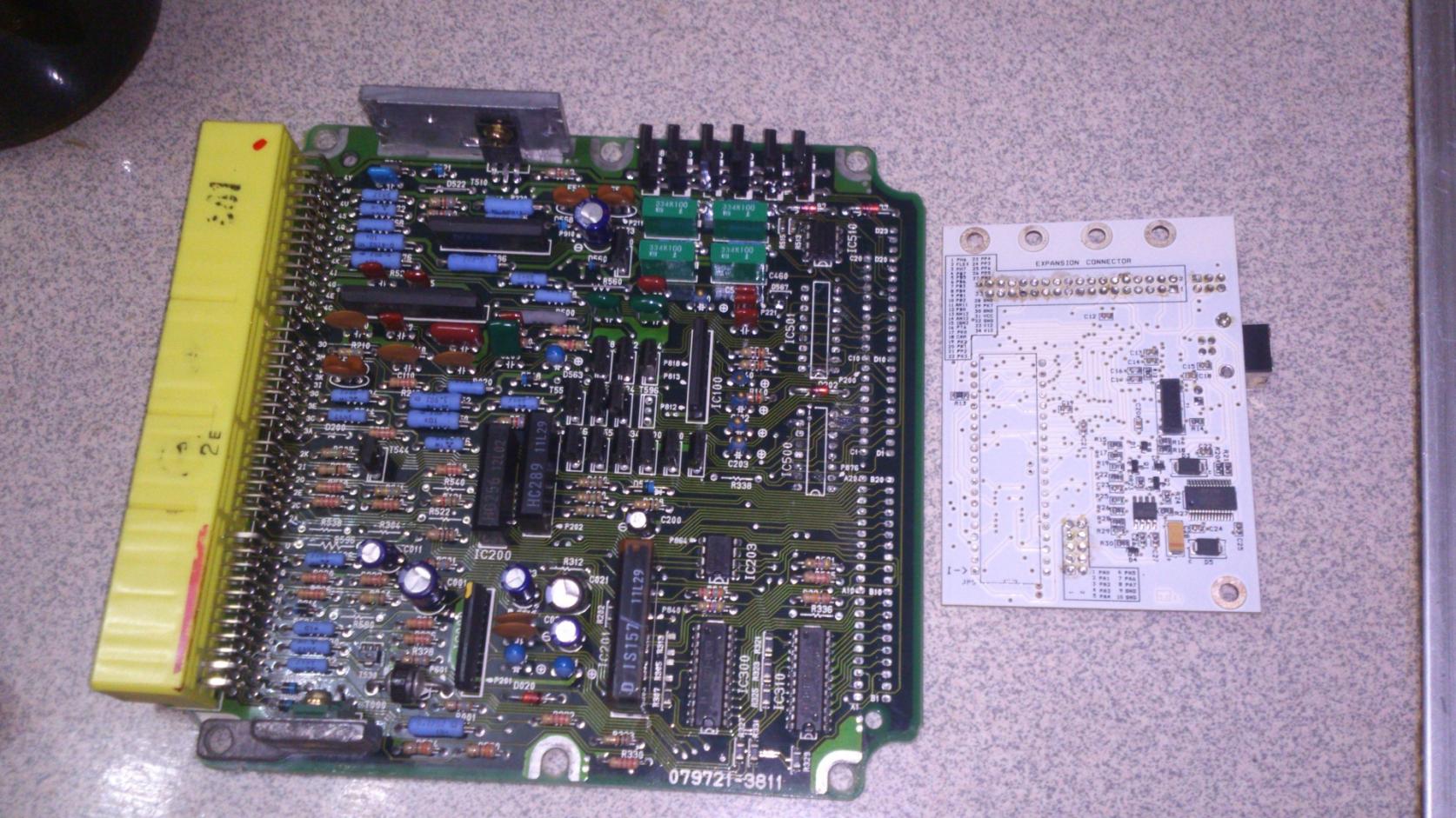
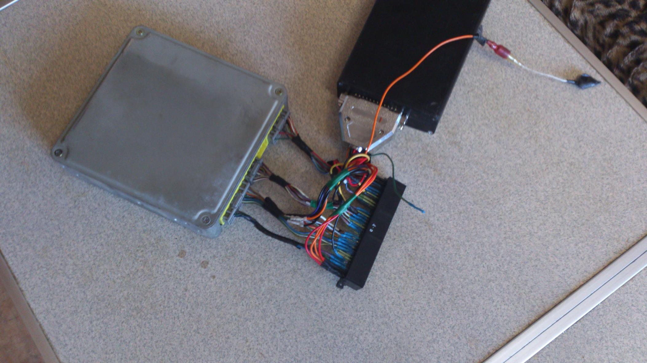
My idea was not to buy complete ms3x + diybob adapter & make harness adaptor. I'm going to integrate MS-3 daughterboard inside stock ecu.
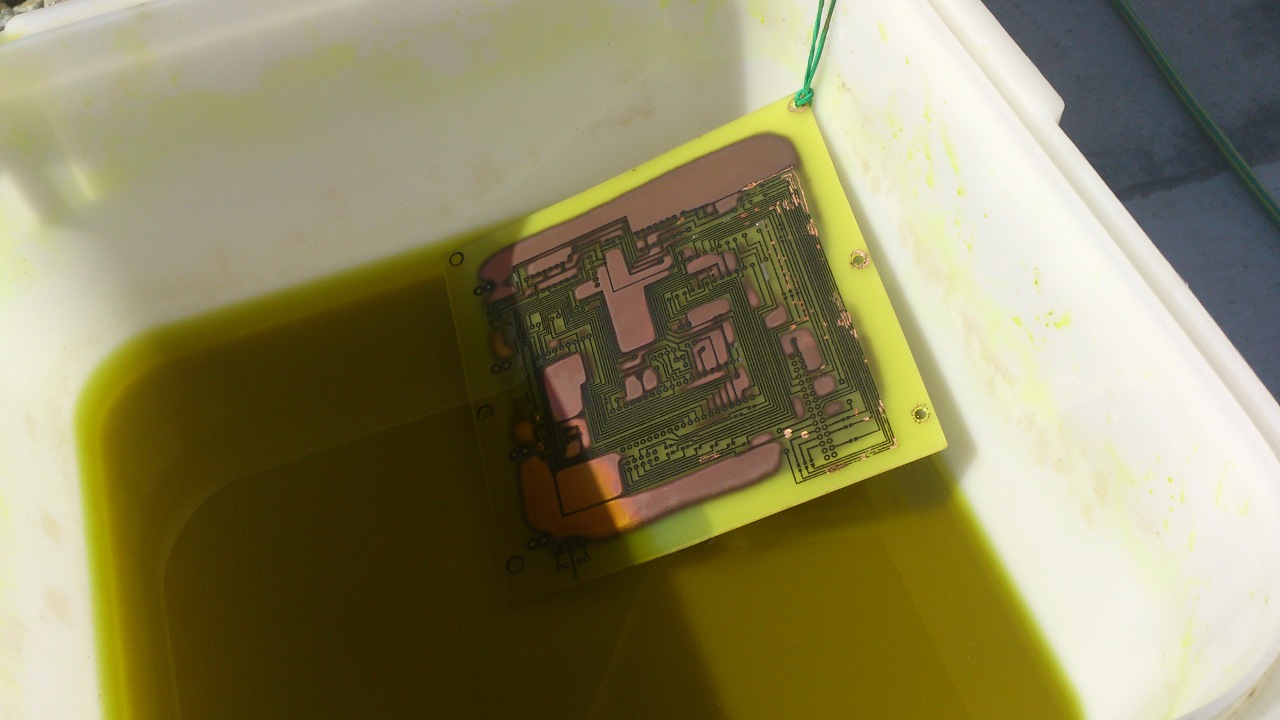
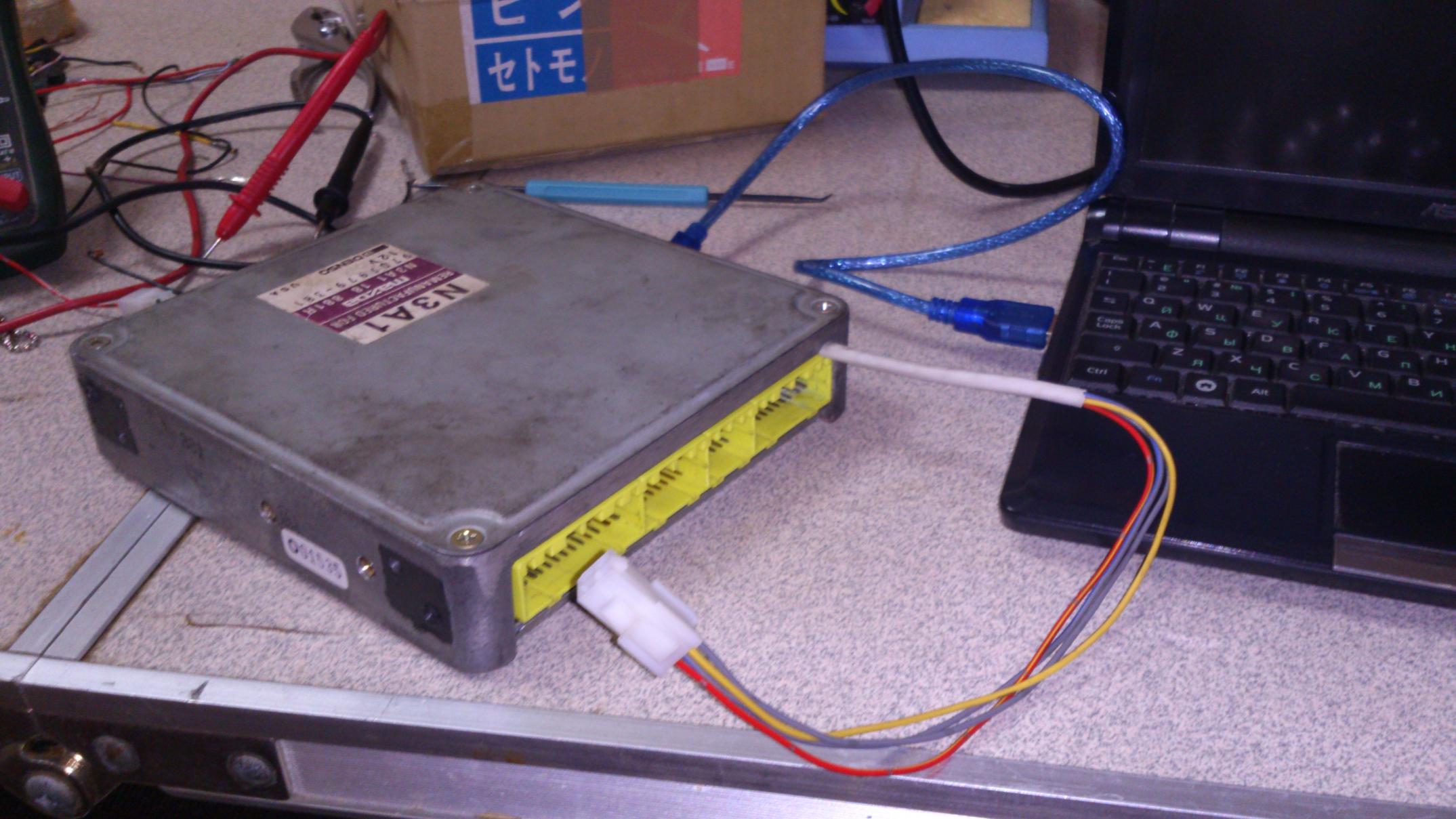
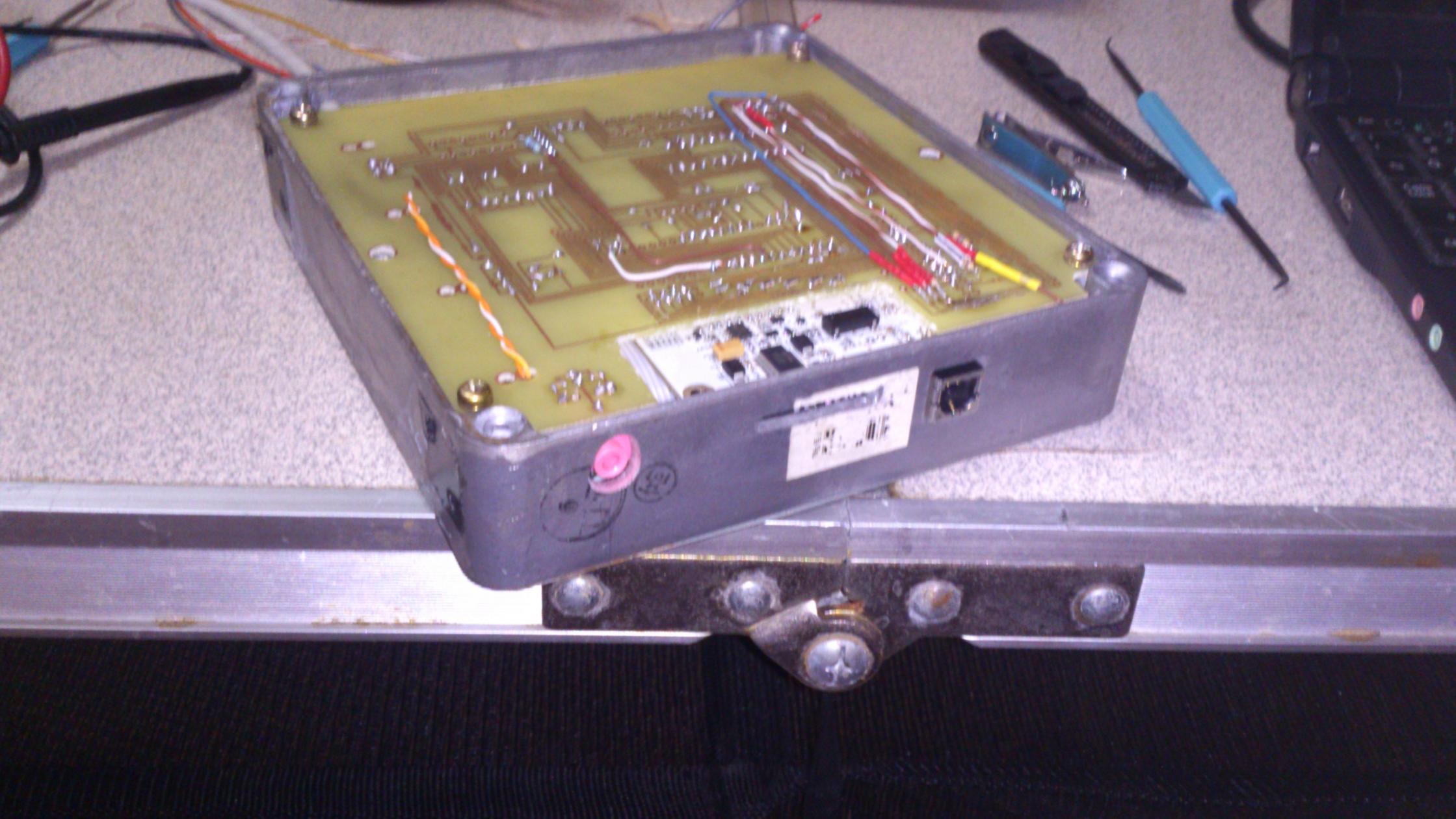
So i disassembled stock ecu & desoldered stock daughterboard, make my own ms-3 daughterboard adapter & assemble all this puzzle.
This is how is's looking:
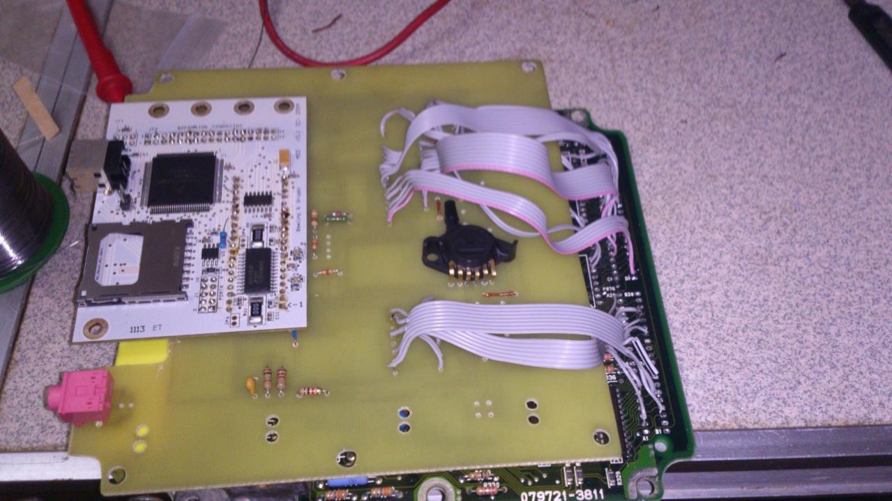
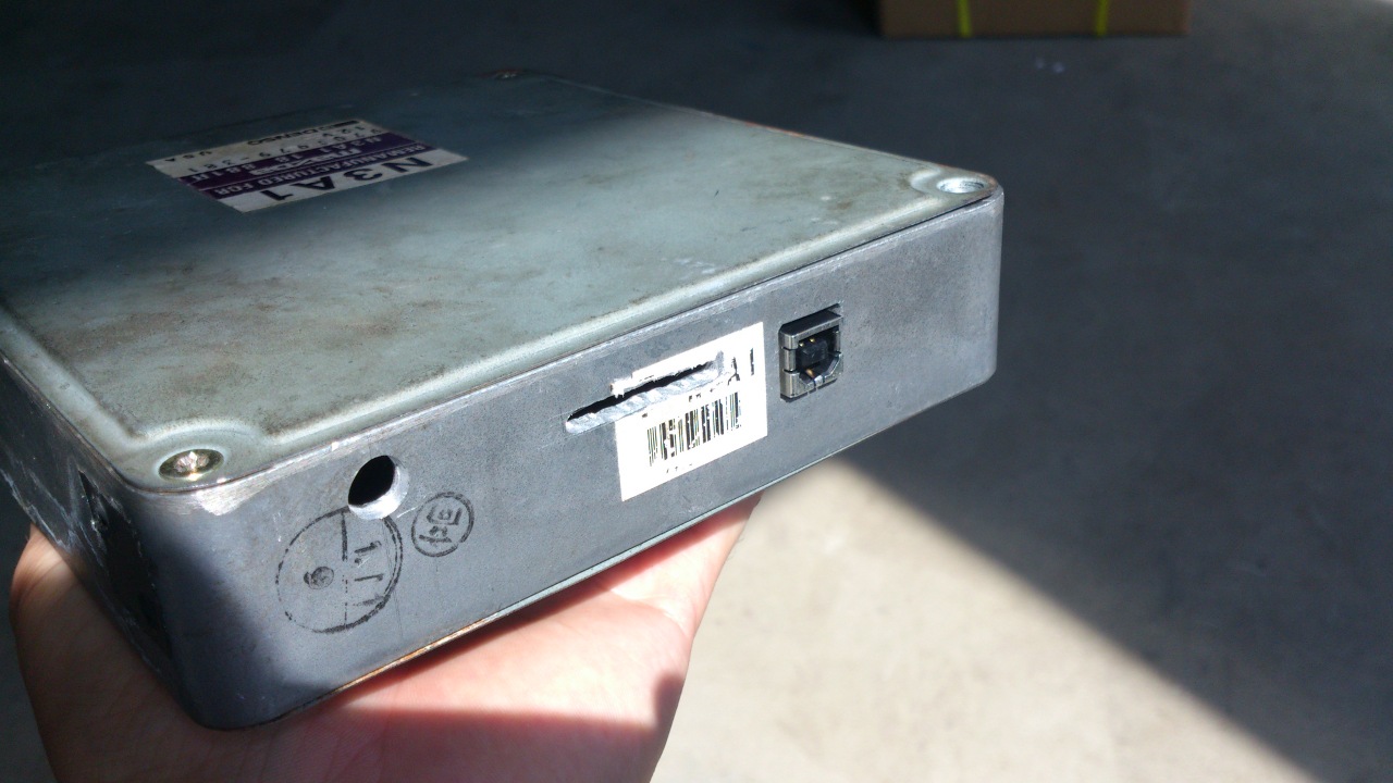
also i added some extra onboard circuits - two EGT amplifiers, baro sensor (cause i do not have datasheet for stock nippindenso baro sensor), headphone socket for listening knock.
This project completed for 90%. engine first start will be soon.
I'm using ms-2 on my FD more than year. Now it's running parallel with stock ecu. stock one controls solenoids, seq. boost, OMP, fan & AC. ms-2 controls idle, ignition & fuel.
So i'm plain to go standalone with ms-3.
My idea was not to buy complete ms3x + diybob adapter & make harness adaptor. I'm going to integrate MS-3 daughterboard inside stock ecu.
So i disassembled stock ecu & desoldered stock daughterboard, make my own ms-3 daughterboard adapter & assemble all this puzzle.
This is how is's looking:
also i added some extra onboard circuits - two EGT amplifiers, baro sensor (cause i do not have datasheet for stock nippindenso baro sensor), headphone socket for listening knock.
This project completed for 90%. engine first start will be soon.
 09-01-13, 07:19 PM
#4
Junior Member
Thread Starter
Join Date: May 2012
Location: russia, vladivostok
Posts: 46
Likes: 0
Received 0 Likes
on
0 Posts
First run:
not only tach. all stock signals (w\o air pump, and switching solenoids) controlled by ms now. Tacho, A/C, A/C shutoff, fan, OMP, double throttle, purge control, charge relief, charge control, turbo control, turbo precontrol, wasgtegate control - al this stuff wired to MS-3. also i have 4 spark outputs because i use ls-2 truck coils in RX-8 ignition mode.
one thing that do not controlled by software now - is OMP. i'm plaining to make patch for ms-3 firmware to support it.
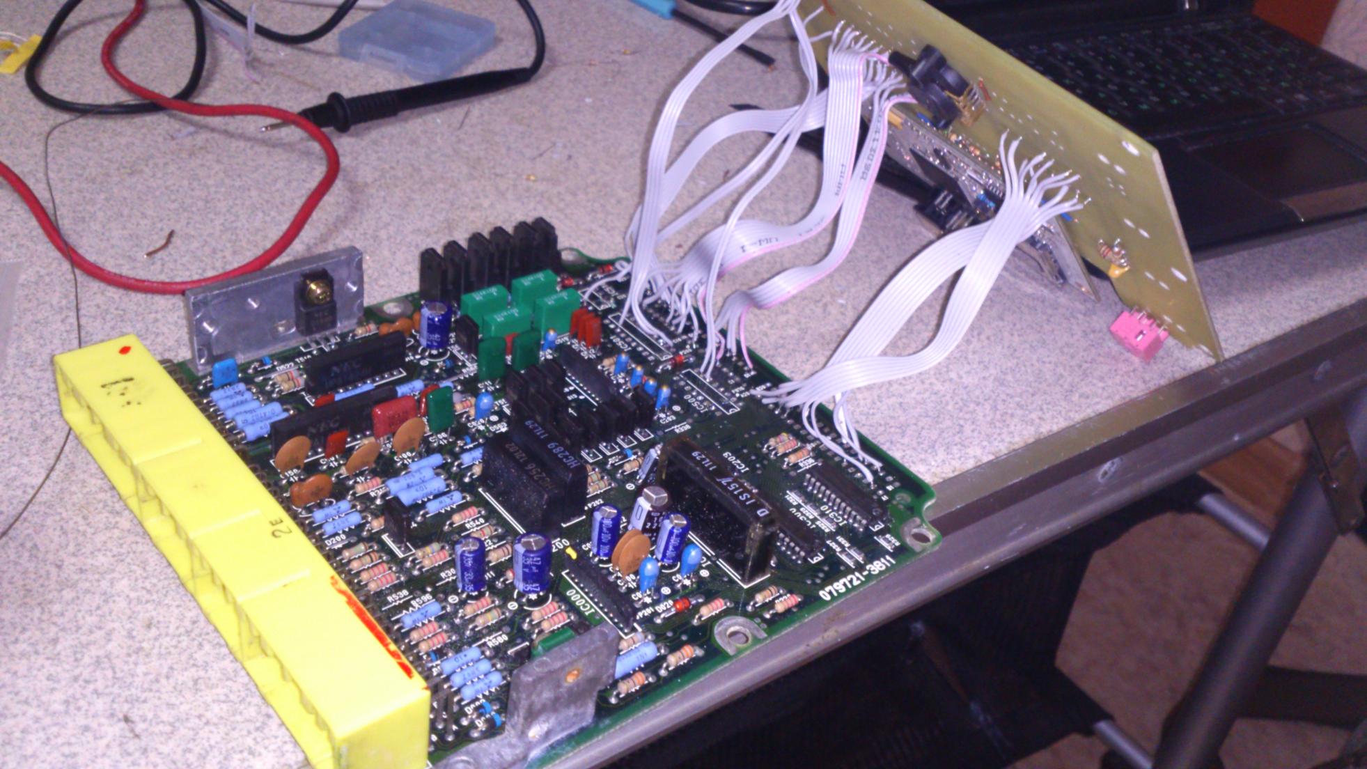
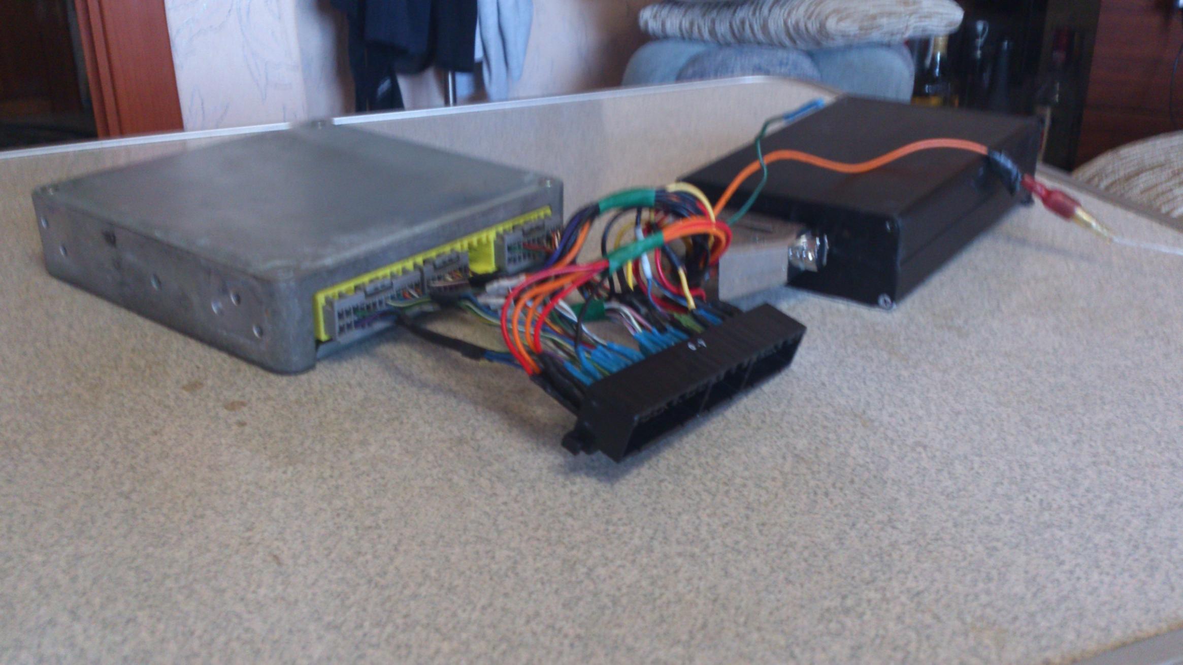
complete look:
my proud is knock listening socket. i'm using extension cord to connect this socket in AUX in on car stereo. Volume up, and listening knock by car speakers very loud and very clean. this is awesome. no one digital knock meter can be so informative.
i sold my ms-2 because it have not enough (for me) I/O. and, yes, i want full sequential setup 
Pics of my previous ms-2:
one tip: black socket is cheap miata socket from diyautotune for 8$. it has only 3 connectors, but for ms-2 setup you will not need connector #2.
one thing that do not controlled by software now - is OMP. i'm plaining to make patch for ms-3 firmware to support it.
complete look:
my proud is knock listening socket. i'm using extension cord to connect this socket in AUX in on car stereo. Volume up, and listening knock by car speakers very loud and very clean. this is awesome. no one digital knock meter can be so informative.
Pics of my previous ms-2:
one tip: black socket is cheap miata socket from diyautotune for 8$. it has only 3 connectors, but for ms-2 setup you will not need connector #2.
09-02-13, 10:00 AM
#5
MegaSquirt Mod
Also keep in mind that the licence for using the ms3 states the MS3 can only be used with a B&G mainboard. Technically you are violating the license.
Ken
09-02-13, 07:02 PM
#6
Junior Member
Thread Starter
Join Date: May 2012
Location: russia, vladivostok
Posts: 46
Likes: 0
Received 0 Likes
on
0 Posts
I am already going to add OMP support in the next month or so. One thing to keep in mind is that the stepper controller on the ms3 may not be able to handle the current requirements of the OMP. The last time I looked into it the amount of current drawn by the OMP was right around the max the chip supported. On an OMP where the windings were at the low end of the spec for resistance, the chip might burn up.
I see. but i'm still using ms3 daughterboard. this is B&G Hardware too. Unfortunatly pure MS3+MS3X installs can not be used to fully replace fd3s ECU in sequential turbo setup. There are too many solenoids. unused injE,F,G,H channels + v3injA,B channels is not enought. you also will need to use unused spark outputs to control solenoids, but MS3X spark outputs too weak to control solenoids directly.
Trending Topics
05-10-15, 10:22 PM
#8
Junior Member
Thread Starter
Join Date: May 2012
Location: russia, vladivostok
Posts: 46
Likes: 0
Received 0 Likes
on
0 Posts
Also i've done with OMP code for MS3 source (years ago).
official MS3 firmware does not have it yet.
if someone interesting, i could share source here.
Last edited by vl-alexander; 05-10-15 at 10:28 PM.
05-11-15, 10:44 AM
#9
Junior Member

Join Date: Nov 2013
Location: Ireland
Posts: 8
Likes: 0
Received 0 Likes
on
0 Posts
Yeah the pinouts between the two standard boards. I'd be very interested in the source. I am currently running a power fc but would be interested in running megasquirt in standard ECU housing.
05-12-15, 07:46 PM
#10
Junior Member
Thread Starter
Join Date: May 2012
Location: russia, vladivostok
Posts: 46
Likes: 0
Received 0 Likes
on
0 Posts
Code:
1A				a1
1B	+12V			a2 5v. d21 12v
1E	A/C sensor			b5
1G	ign tf			c2
1H	ign l			c1
1J	ign tr			d3
1K	fuel pump speed			d15
1L	A/C relay			ic501[12]
1M	Speed sensor			b8
1O	MAP			a15
1Q	Clutch pedal			a6
1U	Fuel temp			b15
2B	Tacho			b14
2I	heat hazard			b3
2K	1st 2nd gear			a9
2L	2nd gear			b9
3A	OMP position			a18
3D	FAN relay			ic500[8]
3E	CLT			b17
3G	TPS			b16
3H	sol. Purge cont			d4
3I	Vref			c3,c4
3L	IAT			a16
3M	knock			c7
3N	ign d16			ic501[9]
3O	sol. double throttle			a20
3P	ign d15			ic501[1]
4C	GND			d10-12, c6,8
4E	NE+ (tooth)			d9,8
4G	G+ (trig)			d7
4I	stepper.omp			ta500 [d14]
4J	stepper.omp			ta500 [c13]
4K	stepper.omp			ta500 [d13]
4L	stepper.omp			ta500 [c12]
4M	ign d14			c11
4N	ign js11			ic500[7]
4Q	IAC			Ic510[7]
4R	sol. Turbo contr			d17
4S	sol. Charge relief			ic501[2]
4T	sol. Charge cont			ic500[6]
4U	boost. WG			d16
4V	boost. Turbo prec			c17
4W	INJ. front prim			d18
4X	INJ. front sec			c19
4Y	INJ. rear prim			d19
4Z	INJ. rear sec			c18
internal baro sensor on pin (b11) (1.04v=30kpa, 4.8v=125kpa)
Note: ta500 (Omp driver) is not just a set of 4 logic gates. If you want this "blackbox" drive only one output at any time, inputs must be set to 0b1000, 0b0010, 0b1110, 0b1011. sorry, but i cant remember acual byte order (which one - d14, or c12 is LSB)
also i am not sure about a2 pin. you should double check and find good 5v source, because, i remember, i had problems with some source, which can not provide enough current to drive MS3 daughterboard.
Last edited by vl-alexander; 05-12-15 at 07:54 PM.
05-13-15, 05:21 AM
#11
Junior Member
Join Date: Nov 2013
Location: Ireland
Posts: 8
Likes: 0
Received 0 Likes
on
0 Posts
Thank You for that, It helps alot. how long did it take you to work out the pinouts? Did you eventually take the 5v source off the board or did you add an extra regulator?
05-13-15, 11:10 AM
#12
Junior Member
Thread Starter
Join Date: May 2012
Location: russia, vladivostok
Posts: 46
Likes: 0
Received 0 Likes
on
0 Posts
Yeah, i found 5v source somewhere on the board. just try to connect some load to every pin starting from a3, and check voltage drop.
just noticed, that pins 3N, 3P, 4M, 4N i marked as ignition one. but actually, this is some emission solenoids like Relief2, switching, and so...
I removed that solenoids, and use theese wires to drive COP by LS2 coils.

Thread
Thread Starter
Forum
Replies
Last Post
The Shaolin
2nd Generation Specific (1986-1992)
9
09-14-15 07:50 PM